background image

2

COOPER LIGHTING SOLUTIONS    

 IB519126EN


 Installation instructions


Installation Instructions – VRVT3 LED Vaportight Luminaire Installation

To Surface bracket Mounted

Snap Over Housing Lip

Snap Brackets Together

Bracket Mounted to 

Surface Structure

Mounting

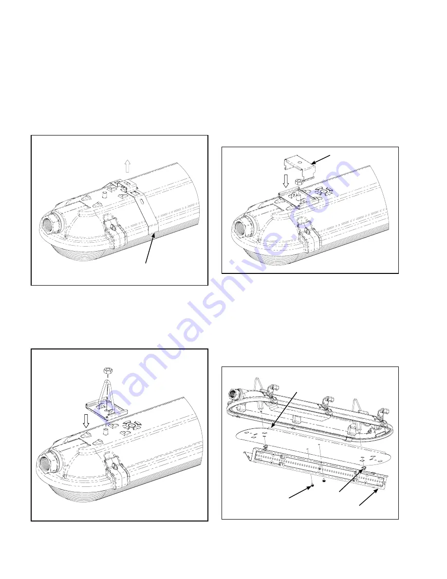
The VRVT3 supports the following 3 mounting options; 

Surface Mount Strap:

 Each unit is supplied with 2 surface 

mounting straps. Locate and space the brackets apart on 

the mounting surface such that they will be equally spaced 

from the fixture ends using appropriate fasteners. The 

housing lip edge can then be snapped onto the mounting 

straps. (Figure 1.)

Figure 1.   

Figure 2.   

Figure 3.   

Figure 4.   

Hanging Loop:

 Option sold separately. Install a hanging 

loop bracket on each stud located on the back of the 

housing using the hex nuts provided. Locate appropriate 

hangers on the ceiling for chain or other mounting hardware 

desired (by others) and attach to loop hangers. (Figure2.)

Modular Surface Mount:

 Option sold separately. The 

modular Surface Mount consists of 2 components; a fixture 

bracket and a surface mounted bracket. Attach a fixture 

bracket to each stud on the back of the fixture using the 

supplied hex nuts. Measure the distance between the two 

studs and properly space the surface brackets apart on the 

mounting surface with appropriate fasteners. The fixture 

bracket can then be snapped into the surface bracket, 

suspending the fixture. (Figure 3.)
Install tamper-resistant screws on each latch.

Interior Access

To access the interior of the fixture, begin by unlatching 

the lens and setting lens aside. The LED gear tray is then 

removed by removing the 2 hex huts. For parking garage 

and wide distribution models the LED V bracket must be 

removed first by removing the two hex screws then slide 

the bracket to disengage the slide lock tabs. The gear tray 

will hang from the safety lanyards. Any wiring connections 

necessary can be made. (Figure 4.)

Sheet Metal Screws (2)  

(P & W Models Only)

V Bracket  

(P & W Models Only)

Hex Nut (2)

Gear Tray

Содержание Fail-Safe VRVT3

Страница 1: ...ture reference NOTICE These instructions do not claim to cover all details or variations in the equipment procedure or process described or to provide directions for meeting every possible contingency during installation operation or maintenance When additional information is desired to satisfy a problem not covered sufficiently for user s purpose please contact your nearest representative NOTICE ...

Страница 2: ...d attach to loop hangers Figure2 Modular Surface Mount Option sold separately The modular Surface Mount consists of 2 components a fixture bracket and a surface mounted bracket Attach a fixture bracket to each stud on the back of the fixture using the supplied hex nuts Measure the distance between the two studs and properly space the surface brackets apart on the mounting surface with appropriate ...

Страница 3: ...ench when tightening any fitting to the hub Assemble the hub through the housing access hole with the O ring on the outside Thread the hub locknut onto the hub and tighten firmly Do not allow the outside portion of the hub and O ring to rotate when tightening Figure 5 6 For general wet location installations and IP65 IP66 IP67 IP69 use the supplied connector hub and install either a suitably rated...

Страница 4: ...t only The remote battery pack is housed separately in a 2ft VRVT housing and connected to the primary unit with a 3ft length of liquid tight conduit and straight fittings with the units pre wired Only the EM unit requires input supply wiring Once in operation and a c power applied connect the 2 red converter connector wires with supplied wire nut The test button indicator light is located in the ...

Страница 5: ...rits ni fournir de directives pouvant répondre à toutes les éventualités pouvant survenir pendant l installation le fonctionnement ou l entretien Si des renseignements additionnels sont nécessaires afin de résoudre un problème insuffisamment décrit selon l utilisateur veuillez communiquer avec votre représentant le plus près de chez vous AVIS Une mise à la terre adéquate est requise afin d assurer...

Страница 6: ...urface avec module Option vendue séparément Ce montage en surface avec module comprend deux 2 composants un support de luminaire et un support de montage en surface Fixez le support de luminaire sur chaque montant situé derrière le luminaire en utilisant les écrous hexagonaux fournis Mesurez la distance entre les deux 2 montants et espacez les supports de surface de part et d autre de la surface d...

Страница 7: ...es raccords au plot Assemblez le plot par le trou d accès du boitier en utilisant un joint torique à l extérieur Vissez le contre écrou du plot au plot et serrez le fermement Évitez tout mouvement de rotation de la partie extérieure du plot et du joint torique lors du serrage Figures 5 et 6 Plot Bague d étanchéité Bague de mise à la terre Corps Garniture d étanchéité Pour des installations général...

Страница 8: ...oitier VRVT de 0 6 m 2 pi et raccordée au luminaire primaire avec un conduit étanche aux liquides de 0 9 m 3 pi et des raccords droits aux luminaires préalablement câblés Seuls les appareils de secours nécessitent une entrée d alimentation électrique Dès la mise en service et le courant continu installé raccordez les deux 2 fils rouges connecteur convertisseur avec les deux 2 capuchons de connexio...

Страница 9: ...ortar directivas para tratar cualquier posible contingencia durante la instalación el funcionamiento o el mantenimiento Cuando se requiera mayor información para tratar un problema que no está cubierto suficientemente para los fines del usuario contacte a su representante más cercano AVISO Es necesaria una correcta conexión a tierra para garantizar la seguridad personal Observe cuidadosamente el p...

Страница 10: ...ular La opción se vende por separado El montaje de superficie modular consta de 2 componentes un soporte de accesorio y un soporte montado en la superficie Fija un soporte de fijación a cada perno en la parte posterior del accesorio utilizando las tuercas hexagonales suministradas Mide la distancia entre los dos pernos y separa correctamente los soportes de superficie en la superficie de montaje c...

Страница 11: ...istrado e instala un cable y agarre de cable WT con la clasificación adecuada o un conducto y accesorios herméticos a líquidos Para IP69 usa solo conductos y accesorios herméticos a líquidos Cuando instales el concentrador aplica una pequeña tira de sellador de silicona alrededor de la esquina interna de la junta tórica y el cuerpo del concentrador antes de instalar el concentrador Aplica sellador...

Страница 12: ...ipment generates uses and can radiate radio frequency energy and if not installed and used in accordance with the instruction manual may cause harmful interference to radio communications Operation of this equipment in a residential area is likely to cause harmful interference in which case the user will be required to correct the interference at his own expense Énoncé de la FCC Remarque Cet équip...

Отзывы: