4
SQN IO&M
B51141-004
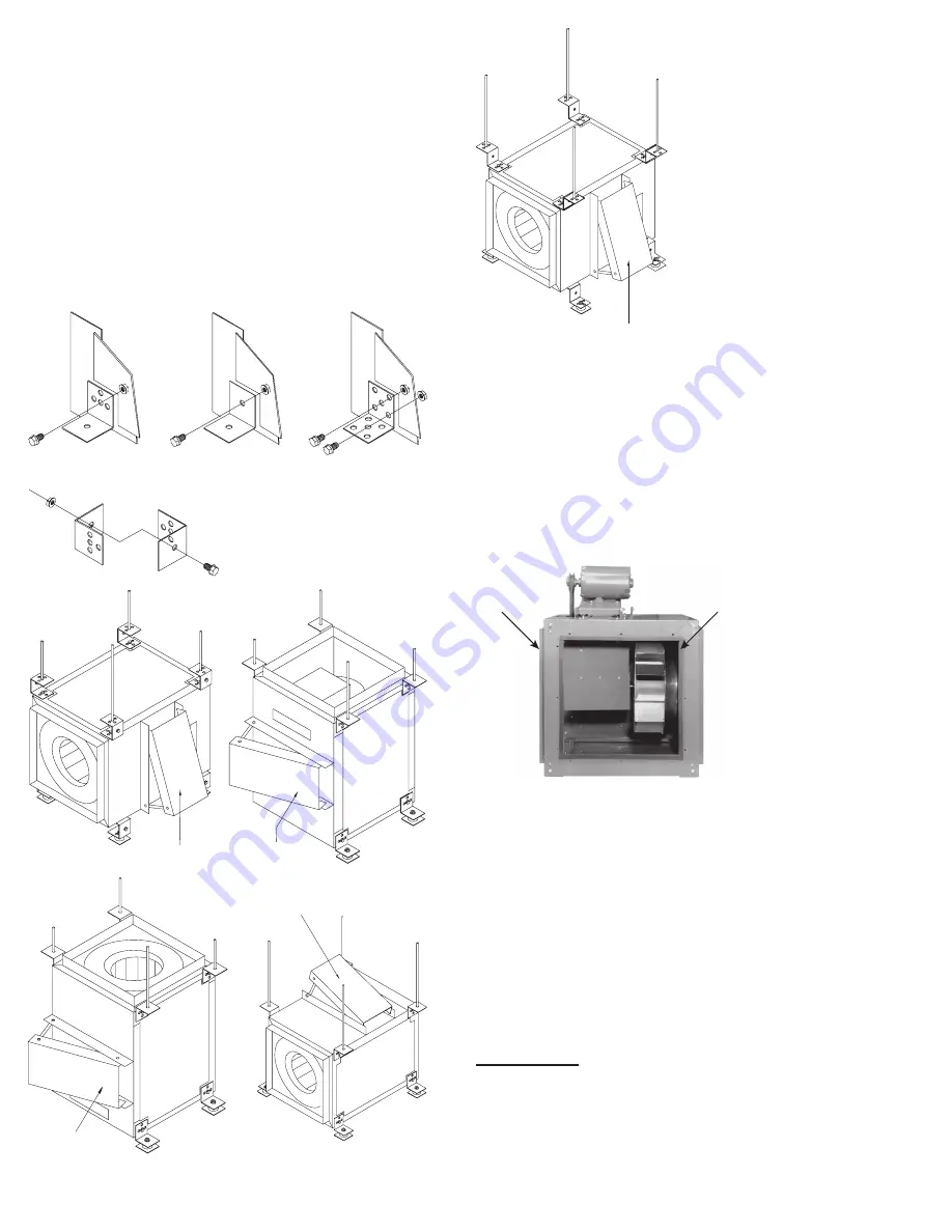
Blower Installation
The fan is shipped with the motor in the 12 o’clock posi-
tion and the feet are shipped loose. (Feet may be under
weather cover)
1. Upon receipt of the fan, remove the eight (8) feet
shipped with the fan and ensure the feet are the cor-
rect type. Refer to
Figure 4
.
2. Determine how the fan is to be mounted. Refer to
Foot
Mounting Illustrations
.
3.
Remove the 5/16” bolt(s) from the corner of the hous
-
ing in which the foot is to be attached.
4. Place the foot over the open bolt hole(s) and bolt the
foot to the unit. Refer to
Figure 4
.
Foot Mounting Illustrations
Sizes 70 - 135
Sizes 150 - 225
Sizes 245 - 402
View of A or E Foot Assembly
Not on direct drive
(A)
Not on direct drive
(B)
Not on direct drive
(C)
Not on direct drive
(D)
Not on direct drive
(E)
SQN Optional Side Discharge Installation
Upon receiving an SQN for a side discharge installation,
please note that the rear discharge block-off panel is in
-
stalled on the unit and that the correct number of side dis-
charge duct connection collars are provided (4 steel flang
-
es for a single side discharge and 8 for dual).
To install the side discharge duct connection collar, re-
move the appropriate access door. Install the side dis-
charge duct connection collar using the bolts that were re-
moved with the access door. Then connect the duct work.
See page 6 for examples.
Rear discharge
block off planel
Side Discharge Duct
Connection Collar
NOTICE! Original Loren Cook Company labels must
remain with the unit. This may require swapping ac-
cess doors from one side to the other.
Final Installation Steps
1. Ensure that all accessories are installed.
2. Ensure that the blower is secured to ductwork.
3. Inspect wheel-to-inlet clearance. Ensure wheel does
not rub against the inlet.
4. Test the fan to ensure the rotation of the wheel is the
same as indicated by the rotation label.
5. Inspect for correct amperage with an ammeter and
correct voltage with a voltmeter.
Operation
Pre-Start Checks
1. Lock out all the primary and secondary power sources.
2. Inspect and tighten fasteners and setscrews, partic-
ularly fan mounting and bearing fasteners. Refer to
Figure 4


