1280x720@60Hz. Within the OSD menu, press to move up and down or
adjust selections within menus.
7.
ENTER:
Press to confirm a selection or to go deeper into a menu item.
Note:
Press and hold the ENTER and MENU buttons for 3 seconds to
enter into firmware update mode. The LEDs will illuminate in sequence
from left to right to indicate the unit is in update mode. Plug a USB
thumb drive containing the updated firmware in the root directory into
the SERVICE port. The LEDs will turn off to indicate the update process
is proceeding. If the update procedure is completed successfully all
LEDs will illuminate together. If the update fails then no LEDs will
illuminate. The unit will automatically reboot after approximately 10
seconds. After completing the upgrade process please verify the
firmware version with in the OSD menu under “INFORMATION.”
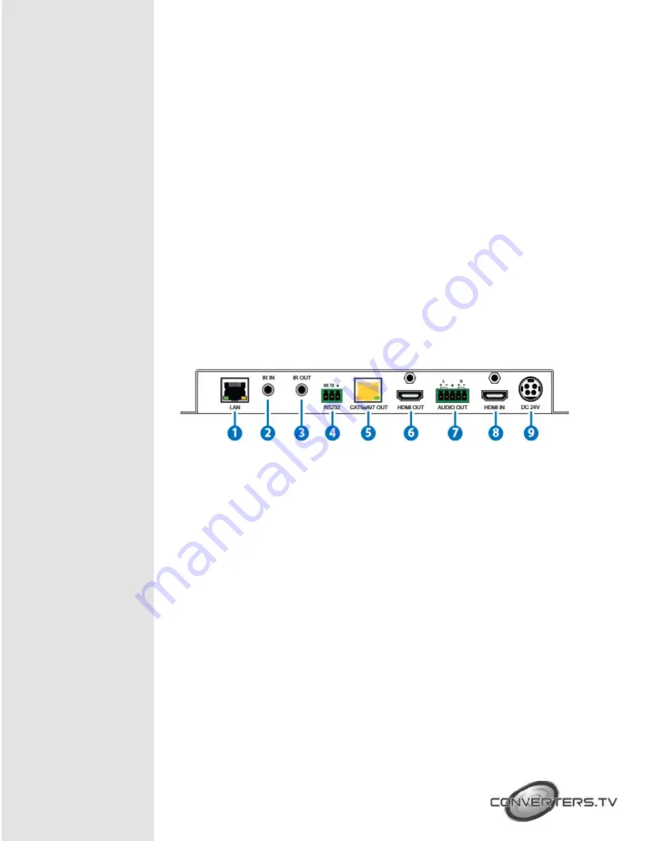
Rear Panel
1. LAN:
Connect to an Ethernet supporting device or to your local network as
appropriate. The yellow LED will illuminate to indicate a successful LAN
connection between the Transmitter and Receiver, however, if the
yellow LED blinks irregularly it indicates a data link error. The green LED
will illuminate when the connected Ethernet speed is 100Mbit/s.
2.
IR IN:
Connect to the supplied IR Extender cable for IR signal reception.
Ensure that remote being used is within the direct line-of-sight of the IR
Extender.
3.
IR OUT:
Connect to the provided IR Blaster to transmit IR signals to devices
within direct line-of-sight of the IR Blaster.
4.
RS-232:
Connect to a PC, laptop or other serial control device with a 3-pin
adapter cable for the extension of RS-232 signals to the Receiver. For
receiving commands from the Receiver side, depending on your
equipment’s pinout, the Tx and Rx pins might need to be reversed.
5.
CAT5e/6/7 OUT:
Connect to the Receiver unit with a single Cat.5e/6/7 cable for
transmission of all data signals. The output resolution can be different
Содержание 15461
Страница 1: ...HDMI to HDBaseT Scaler with Audio Output ID 15461 Operation Manual ...
Страница 15: ...Connection Diagram ...


