background image

ACAM_64 


  4 


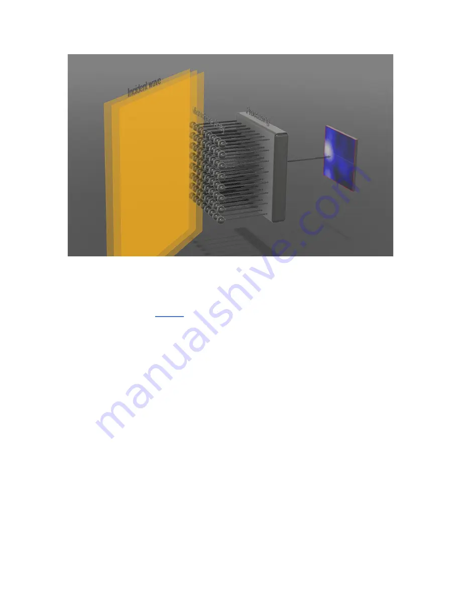
Figure 1 

An array of microphones captures the sound waves hitting the array from many different directions. For 

every pixel, a massively parallel digital processing engine applies specific delays, and sums the acoustic 

signals from every microphone, so that the signals from a specific angle of incidence (azimuth and 

elevation) arrive in phase. 

Figure 1

 shows that process for a single pixel. Note that a different and 

precisely adjusted delay must be applied to every path, from every microphone in array to every pixel in 

the image. In the simplest implementation, the intensity of every pixel is calculated as the energy of that 

sum signal, averaged over a specific length of time. 

3.1


Frequency, Aperture Size, and Image Resolution 

For an optical camera, as well as for an acoustic camera, the image resolution is a proportional to the 

ratio of aperture size to wavelength. 

For an optical camera the aperture size of the camera (the size of the lens or more generally the light 

collector) is always very large relative to the wavelengths of interest. This is true even for very small 

lenses, such as those found in camera phones, where the size of the lens is a few mm, while the 

wavelengths of interest are in the hundreds of nm (more than 10000 times smaller). For an optical 

camera, resolution is rarely limited by the size of the aperture. 

For an acoustic camera on the other hand, the frequencies of interest often extend to  quite low 

frequencies (long wavelengths). For instance, the wavelength at 100 Hz is 3.4 m. To have a reasonable 

resolution at such low frequency would require an array of at least 8 to 10 times as large (25 to 30 m 

wide). This is usually not practical. Therefore, for acoustic cameras the resolution is typically poor at lower 

frequencies and improves only as the frequency of interest increases. 

3.2


Spatial Sampling and Upper Frequency Limit 

For an acoustic camera, the maximum frequency is limited by the spatial separation between two 

adjacent microphones. The half wavelength of the maximum frequency sampled by the microphones 

must be wider than the distance between two microphones. Otherwise, the array is not able to distinguish 

Содержание ACAM 64

Страница 1: ...ACAM_64 User s Manual December 18 2021 Bruno Paillard ...

Страница 2: ...____________________________ 8 7 2 1 Image Field ________________________________________________________________ 8 7 2 2 Cursors____________________________________________________________________ 8 7 2 3 Instrument Information Fields __________________________________________________ 8 7 2 4 Frequency Response _________________________________________________________ 8 7 2 5 Frequency Response C...

Страница 3: ...TING ________________________________________ 10 8 1 USB Driver Installation_________________________________________________________ 10 8 2 Electrostatic Discharges ________________________________________________________ 10 ...

Страница 4: ...n excess of 160 dBSPL 3 Theory of Operation An acoustic camera produces an image where the intensity of each pixel represents the amplitude of acoustic waves coming from the corresponding direction This is akin to an optical camera producing an image where each pixel represents the intensity of light coming from the corresponding direction For an optical camera the lens focuses light coming from a...

Страница 5: ...light collector is always very large relative to the wavelengths of interest This is true even for very small lenses such as those found in camera phones where the size of the lens is a few mm while the wavelengths of interest are in the hundreds of nm more than 10000 times smaller For an optical camera resolution is rarely limited by the size of the aperture For an acoustic camera on the other ha...

Страница 6: ...to be listened to This process is called beamforming The microphone array can be digitally steered to the angle of incidence corresponding to any pixel in the field of view and focus on that source In addition since the image shows the azimuth and elevation of the loudest source in the field of view of the camera the beamformer can be made to follow that hot spot as it moves across the field of vi...

Страница 7: ... to an available USB port on the PC 2 Verify that the PC properly detects the instrument and wait for the PC to load the driver In case of doubt see section Troubleshooting 6 3 Initial Test and Configuration 1 Upon connection to the PC the LED should light up red yellow then green The LED turning green means that the instrument has finished its boot procedure and that the PC has recognized it 2 Go...

Страница 8: ...nse controls 6 Trace of past levels in dB 7 Image persistance control 8 Lin Log image mapping 9 Image interpolation button 10 Image palette 11 Auto Track button 12 Field of view button 13 Record button 14 Play back button 15 Pause button 16 Scrubber bar 7 1 Starting the Application To control an ACAM_64 using the Instrument_Manager proceed as follows 1 3 4 6 7 14 5 8 9 10 11 12 13 16 16 2 ...

Страница 9: ... shows the level measured at the position of the cursor 7 2 3 Instrument Information Fields These fields present information about the instrument The User_ID can be set to any alphanumeric string limited to 32 characters This is used to identify the instrument to something pertinent to the user 7 2 4 Frequency Response This shows the frequency response of the camera 7 2 5 Frequency Response Contro...

Страница 10: ...ton When this button is pressed the audio beamformer will track the highest intensity pixel in the image The audio produced by the camera will automatically follow and focus on the source as it moves across the field of view When the mode is not set to AutoTrack the cursor can be moved manually to any pixel in the image 7 2 12 FOV Button The user can choose between two fields of view 60 deg or 90 ...

Страница 11: ...a different PC and or with a different USB cable If the PC does not recognize the instrument go to step 5 5 If the PC does not seem to recognize the instrument open the Device Manager on the PC This is usually found in Control Panel System and Maintenance 6 Just after connecting the instrument to the PC observe that the Device Manager window refreshes 7 Verify that the following 3 items are create...

Отзывы: