24
OPTIONAL REMOTE ANNUNCIATOR INSTALLATION
Please read this entire instruction set before installing!
Turn off all power before installing or servicing!
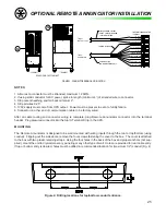
Figure 1: Remote Annunciator
Figure 2: Rear of Remote Annunciator showing J1
and terminal header
WIRING
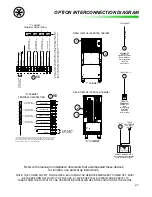
The wiring of the Remote Annunciator consists of two feeds. One being the communication cable supplied with the
unit, and the other is 120Vac 50/60Hz from the output of the UPS it is monitoring. The power supply can be taken
directly from an output breaker on the unit, a receptacle or panel that is fed by the UPS or a nearby emergency light-
ing circuit fed by the UPS. From the UPS, run the communication cable to the location of the Remote Annunciator.
The cable may be run through conduit, walls or cable tray/raceway, but care must be taken not to pinch, cut or kink
the cable. After the cable is run, trim excess cable or coil in a safe location. Both feeds, after entering the box, must
be wired to the supplied connector as shown in Fig 3. Use standard 1/2” box connector clamps to anchor the wire
to the box (not supplied).
REMOTE ANNUNCIATOR
Controlled Power Company’s Remote Annunciator is capable of displaying status conditions of an Uninterruptible
Power Supply and alarming under critical conditions. The following installation instructions include operation, wir-
ing, and mounting your Remote Annunciator.
OPERATION
During normal operation of the UPS, the Remote Annunciator will illuminate the green UPS On LED. During an
alarm condition (unit over temperature, utility fail, etc.) the red General Alarm LED will illuminate along with other
applicable LED’s indicating the nature of the alarm and the audible alarm will sound. The audible alarm can be
silenced by pressing the Alarm Silence button on the front of the unit. If another alarm condition occurs (i.e. low
battery), the alarm will resound. The Battery Test Active LED will illuminate when the UPS is running a Manual
or Automatic, Monthly or Annual battery test, but no alarm will sound for this condition. The audible alarm can be
altogether defeated by changing jumper J1 on the circuit board. See the back side of the Remote Annunciator for
J1 jumper setting.
Содержание MODEL ES
Страница 51: ...51 APPENDIX A RELATIVE DRAWINGS SCHEMATICS APPENDIX A ...
Страница 57: ...57 NOTES ...


