Unidrive Regen Installation Guide
1
Issue Number: 2
www.controltechniques.com
1
Introduction
Any standard Unidrive can be configured as an AC Regenerative Unit (hereafter referred to as Regen drive).
This Installation guide covers the following:
•
Principles and advantages of operation in Regen mode
•
Details of additional components required
•
Configuration of Regen systems
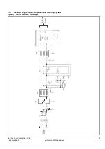
At least two Unidrives are required to form a complete Regenerative system - one connected to the supply and the second one to the motor. A
Unidrive in Regen mode converts the AC mains supply to a controlled DC voltage which is fed into other drive(s) to control a motor.
Figure 1-1
Regen drive system connection
1.1
Principles of operation
The input stage of a non-regenerative AC drive is usually an uncontrolled diode rectifier, therefore power cannot be fed back into the AC mains
supply.
In the case of a Unidrive operating in Regenerative mode, the IGBT bridge is used as a sinusoidal rectifier, which converts the AC supply to a
controlled DC voltage. This DC voltage can then be used to supply one or more Unidrives which control motors, commonly known as motoring drives.
A Regen drive produces a PWM output voltage which has a sinusoidal fundamental at an amplitude and phase which are almost the same as those
of the AC supply voltage. The difference between the drive PWM line voltage and the supply voltage occurs across the Regen drive’s inductors. This
voltage has a high frequency component which is blocked by the Regen inductor and a small sinusoidal component at line frequency. As a result,
currents flowing in these inductors are sinusoidal with a small high frequency ripple component.
N
Terminals L1, L2 and L3 and the associated diode rectifier are not connected and are redundant on drives used in a Regen configuration.
Figure 1-2
Phasor diagram
Additional
Circuitry
Regen Drive
Motoring Drive
M
R
3 Phase
Supply
Y
B
Regen
Inductor
U
V
W
AC
DC
+DC
-DC
+DC
-DC
U
V
W
AC
DC
NOTE
V
s
Supply Voltage
V
r
Voltage at line terminals of Regen drive
j
ω
LI
r
Voltage across Regen Inductor
I
r
Current at line terminals of Regen drive
Power flow from supply
Power flow back to supply


