Unidrive Regen Installation Guide
31
Issue Number: 2
www.controltechniques.com
A.4
Regen and motoring drive ratings
N
The Regen drive’s current limits are set at 150% and are not adjustable.
In general the Regen drive must be rated at a power greater than, or equal to, the maximum braking power.
Example:
•
Two 30kW motoring drives are each driving 30kW motors. The load is such that only one drive is braking at a time.
If each motor supplies between 20 and 30kW motoring, and the braking power varies from 0 to 30kW, the maximum total braking power is 30 - 20 =
10kW, which is what the Regen drive should be rated for.
In drive configurations where the motoring drive power rating is several times the expected braking power, it is necessary to consider the peak
braking power returned from the load.
Example:
•
The motoring drive is a 75kW Unidrive. Motoring power is 75kW. Steady state braking power is 20kW.
From these figures, it may appear that a 22kW Regen drive will provide sufficient braking power. However, dynamically the peak braking power could
be much greater. If the 75kW drive current limits are set at 150% for motoring and braking (default settings), the peak brake power could be:
√
3
×
156A
×
400V
×
150% = 162kW
This is much greater than the 22kW Regen drive is able to return to the supply, hence a larger drive is required.
N
If the Regen drive is not rated for the required braking power, then the drives will trip on DC bus over-voltage.
A.5
Power circuit connections and components
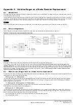
Figure A-2 shows the power connections required when using a Unidrive, operating in Regen mode as a dynamic brake resistor replacement. The
Regen drive control terminals are connected as shown in Figure A-3.
Table A-1 shows the key to the following system layout diagram.
Table A-1
Key to Figure A-2
E
Ground connection point
RFI
EMC filter
I.Tx
Isolated transformer
SFFL
Switching frequency filter inductor
L regx
Regen inductor
V1, V2, V3
Varistor network 550V (line to line)
V4, V5, V6
Varistor network 680V (line to ground)
Rsx
Softstart resistor
Fsx
AC supply fusing
SFF Cx
Switching frequency filter capacitor
Rdx
Switching frequency filter capacitor discharge resistor
Tcx
Thermocouple
K1
Supply contactor
K2
Main contactor
K3
Auxiliary contactor
MCB1x
Switching frequency filter capacitor MCB
aux1x
Switching frequency filter MCB auxiliary through which Regen drive enable is
connected
aux2
Main contactor auxiliary for “main contactor closed signal”
aux3
K3 auxiliary with coil supply for K2
Ovld
Thermal, Magnetic overload
NOTE
NOTE

