background image

Содержание CDC 722-10

Страница 1: ...l c CONT OL DATA I r J CO OR TION 62940003 CDC 7 22 10 20 DISPLAY TERMINAL CC628 A HARDWARE MAINTENANCE MANUAL SITE INFORMATION...

Страница 2: ...s appendix B Manual revi ed to incorporate ECO 14530 in its final form and to make editorial and technical corrections Interim change manual revised to incorporate ECO 14675 Manual revised to incorpor...

Страница 3: ...ight of the series number is an FCO number If that number and all of the numbers underneath it match all of the numbers on the equipment FCO log then this manual accurately reflects the equipment EQUI...

Страница 4: ...1...

Страница 5: ...changed PAGE Cover Title Page ii thru vi vii viii ix and x xi xii 1 1 1 2 1 3 2 1 2 2 2 3 2 4 2 5 2 6 2 7 and 2 8 2 9 3 1 thru 3 4 3 5 3 6 3 7 thru 3 9 4 1 4 2 5 1 thru 5 4 5 5 5 6 5 7 5 8 5 9 5 10 5...

Страница 6: ......

Страница 7: ...SAM Listings Section 5B Maintenance Procedures Section 6 Parts Data Appendix A Special Cables for Use with Terminal Appendix B Generating Commands in Advanced 752 Mode Other manuals providing referenc...

Страница 8: ...r I...

Страница 9: ...NE LOCAL Switch _ 2 5 MANUAL RELEASE Switch 2 5 Mode Select Switches _ _ 2 5 NORMAL TRANSPARENT Switch 2 6 NORMAL DATA ONLY Switch __ 2 6 PARITY ENABLE PARITY DISABLE Switch 2 6 1 STOP BIT 2 STOP BITS...

Страница 10: ...oni tor Control Problems 5A 3 SAM CRT3 Diagnostic Sel f Test Errors 5A 5 Procedure CRTl Power Application Removal 5B l Procedure CRT2 Hood Removal Replacement 5B l Procedure CRT3 Video Adjustments 5B...

Страница 11: ...r Locations 3 8 5 MAINTENANCE 5 1 5 2 5 3 5 4 CRTI CRT2 CRT3 CRT4 CRT5 CRT6 CRT7 CRT8 CRT9 CRTIO Location of Major Assemblies 5 5 ROM Character Display Example 5 9 Switch Panel Test Presentation Order...

Страница 12: ......

Страница 13: ...ons PHYSICAL DESCRIPTION The display terminal figure 1 1 is a remotely located micro processor controlled input output device The terminal contains a 12 inch diagonal measurement crt and associated dr...

Страница 14: ...module also contains the power supply rectifiers and regulators for the various internal dc volt ages The display module is a crt video display device that uses a raster scan technique to produce a n...

Страница 15: ...isplay Format Display Area Nominal Refresh Rate Display Memory Size Transmission Speeds 62940003 F 376 mm 14 8 in 429 mm 16 9 in 533 mm 21 in 16 78 kg 37 1b 19 9 kg 44 1b 120 220 240 Vac 50 60 Hz at 0...

Страница 16: ......

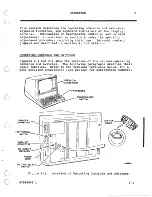
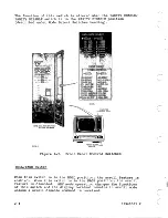
Страница 17: ...ure requiring their use Internal control jumpers are described in section 3 Installation OPERATING CONTROLS AND SWITCHES Figures 2 1 and 2 2 show the location of the various operating controls and swi...

Страница 18: ...nd 128 Vi the 220 V position for between 191 and 235 Vi and the 240 V position for between 208 and 256 V After a snap in cover is removed the switch can be set using a straight slot screwdriver while...

Страница 19: ...switch positioned toward front of terminal restores the signal connections to their proper pins CONTROL SWITCHES The various control switches of the display terminal are shown in figure 2 2 The contr...

Страница 20: ...0 BAUD POWER ON OFF OllTa SWITCH Figure 2 2 Front Panel Control Switches ROLL PAGE Switch When this switch is in the ROLL position the scroll feature is enabled When this switch is in the PAGE positio...

Страница 21: ...allows checking the operation of the terminal without communicating with the modem The transmit circuits are disabled and keyboard data is displayed on the crt In the ON LINE position keyboard data is...

Страница 22: ...be on in order to copy received data When this switch is in the DATA ONLY position the terminal dis regards the RS 232 C CCITT V 24 modem control signals Data Terminal Ready operates normally PARITY...

Страница 23: ...position a carriage return operation positions the cursor to the beginning of the current line A line feed is not performed In the AUTO LF position a line feed operation and a carriage return operati...

Страница 24: ...a power on application and is switched off when local mode is activated DTR CONSTANT DTR SWITCHED Switch The DTR CONSTANT position of this switch causes the DTR signal to be in the on condition In the...

Страница 25: ...is listed in the preface of this manual KEYBOARD INDICATORS Two indicators are located on the keyboard as shown in fig ure 2 3 The LOCK keyboard locked indicator lights during a print operation and fo...

Страница 26: ..._ J 1 I _ _ _...

Страница 27: ...ri ginally received from the factory If the logic power supply module is to be returned for repair use the materials specified in the packaging instructions of figure 3 2 Packaging materials may be ob...

Страница 28: ...N DISPLAY TERMINAL 4 PLACE DISPLAYTERMINALWITH END FRAME CUSHIONING INTO EXTERIOR CONTAINER 5 LOCK L BLOCKS IN POSITION 6 SECURE POWER CABLE IN SLITS OF END FRAMES 00 NOT LET PLUG DANGLE 7 CLOSE AND S...

Страница 29: ...ODULE IN ANTISTATIC BAG WITH MODULE HEAT SINK AT OPEN END OF BAG SEAL BAG WITH TAPE 3 PLACE BAG CONTAINING MODULE INTO CONTAINER WITH HEAT SINK FACING UP AND LOCATED AT HINGED END OF CONTAINER 4 CLOSE...

Страница 30: ...mum of 50 mm 2 in Unshielded high power or high energy wiring may require a larger separation Cabling may be run in the same conduit as telephone lines The customer is responsible for p oviding the I...

Страница 31: ...iguration and to provide a record for maintenance personnel Keep a copy of the record with each terminal DATA RATE SELECT POSITION SWITCH 000000 O E J 0 00000ggggg22 2 NAME nOOOC l X D QOlOlcnOlOlOl N...

Страница 32: ...ers to grasp jumper NOTE Only the NORMAL CURRENT LOOP and Cursor Home Position jumpers are subject to change during installa tion Do not change any other jump ers The functions established by these ju...

Страница 33: ...CJ LOGIC POWER SUPPLYA IOARO 01106 1 FRONT CURRENT NORMAL LOOP Figure 3 4 NORMAL CURRENT LOOP Jumper Location TOP o o FIRST LINE C HOME POSITION o 0 o 0 o 0 o 0 o 0 o 0 o 0 J o 0 o 0 o 0 o 0 o 0 o 0...

Страница 34: ...s contained in section 58 3 8 1 Apply power to display terminal procedure CRTl 2 Observe display screen for power on test failures Troubleshoot any test errors per SAM CRT3 If a terminal power on prob...

Страница 35: ...on 13 Check sound level of audio alarm by performing a CONTROL G function at keyboard To adjust remove hood procedure CRT2 and adjust R7 on logic power supply board 14 Return ON LINE LOCAL switch to O...

Страница 36: ..._ _ r...

Страница 37: ...GRAMS tAM This section contains only the interconnection diagram for the display terminal Logic diagrams are contained in a separate support information manual see preface for publication number 4 62Y...

Страница 38: ...TO LOGIC _ pp cm_ a cn C r 2 IZc n a I aN o oCICII c c c cn CI _ m C NNNN IOoo otCr n WN C MO 0 G 0 C z r C OICIC OI O I lllnIC OI O 11 1 1 1 0 c o I I N NN ca ONC W I N N N I I I II J I _ I L ____ _...

Страница 39: ...nder the following major headings General Maintenance Information Diagnostic and Corrective Maintenance GENERAL MAINTENANCE INFORMATION The following paragraphs provide information that the customer e...

Страница 40: ...reduction or loss In either case CE can notify responsible party common carrier or customer of problem c Decide that an error in operating procedure rather then equipment failure is probably cause of...

Страница 41: ...djustments are being made to terminal when power is applied Always turn power off and disconnect ac power cord when removing replacing components or cables MAINTENANCE TOOLS AND MATERIALS The maintena...

Страница 42: ...to be used for correct ing the malfunction Refer to the Diagnostic and Corrective Maintenance heading for organization of this material LOCATION OF MAJOR ASSEMBLIES Figure 5 1 shows the location of th...

Страница 43: ...AC INPUT TRANSFORMER 03890 1 Figure 5 1 Location of Major Assemblies HORIZ WIDTH coil LI02 adjusts horizontal display width FOCUS control R415 adjusts focus of displayed data BRITE control R412 adjus...

Страница 44: ...low provides overload protection for the 20 V ac transformer outputs feeding the 15 V power supply Fuse F4 1 5A Slow Blow provides overload protection for the 15 9 V ac transformer output feeding the...

Страница 45: ...he failure mode does not prevent display Program Memory Routine determines if the internal pro gram coding is as intended Proper coding results in the message LRC BO OK and LRC Bl OK being displayed I...

Страница 46: ...e is accomplished by pressing the MANUAL RELEASE switch again 5 8 The RAM test is modified to halt on error with the cursor positioned to the error Rosition Continuation of the test following a failur...

Страница 47: ...outine pressing any key causes each character position on the crt to be filled with the data word or control code entered Function keys cause the entry of characters corresponding to the code transfer...

Страница 48: ...sic SAM format Any applicable assumptions or advisory information is provided in the header information of the SAM To interpret a SAM start at the top of the page and determine the response for the fi...

Страница 49: ...T ACTION OF A NUMERICAL SEQUENCE OF ACTIONS IN A GIVEN COLUMN UNDERLINE ALSO USED TO INDICATE THAT ONLY ONE ACTI N IS TO BE PERFORMED INDICATES SAM IS CONTINUED ON PAGE 2 COLUMN B 62940003 C 005 006 0...

Страница 50: ...I I...

Страница 51: ...i I 1 SAMS SECTION SA _ _ _ _ _...

Страница 52: ......

Страница 53: ...gic power supply board Pin 2 is 15 V and pin 3 is return Do not use chassis for ground when measuring 15 V Y N Is 12 V low or missing Measure at IC pins of A4 or A7 Pin 14 is 12 V pin 7 is ground 1 I...

Страница 54: ...al I I I I 011 1 I Reset circuit breaker and retry I I 012 I 1 Replace logic power supply board procedure CRT8 Note I that fuses provide secondary protection and if blown I indicate a solid failure th...

Страница 55: ...mmunication problem I Y N Is there a printer control problem I I I I I 1 I I I I 2 1 I I I 2 I I I I I I I I 4 3 I I I I 5 4 T Basic operational checks are OK Call for assistance if other problems exi...

Страница 56: ...ontrol for open circuit proce I dure CRT10 Replace if open I 020 2 Check for lit crt filament If unlit check for lS V I filament voltage at pin 3 brown wire of crt socket I use J8 pin 3 for ground sid...

Страница 57: ...rd procedure CRT8 Replace switch panel assembly procedure CRTll Is there a switch panel test error Check interconnecting cables Check for interference with switch mechanisms Replace switch panel assem...

Страница 58: ......

Страница 59: ...PROCEDURES SECTION 58 C...

Страница 60: ......

Страница 61: ...ever indicates power is on 2 Remove power by pushing power on off switch lever back in Red orange stripe on top of switch lever is not visible with power off SWITCH LEVER Figure CRTI Power On Off Swit...

Страница 62: ...esent at the high voltage assembly and crt anode lead Use caution when performing the following adjustments 1 Turn terminal power on procedure CRTl and allow a 15 minute warm up period before performi...

Страница 63: ...g magnets to center raster within crt screen figure CRT4 Note adjust R412 to obtain visual raster 11 Adjust VIDEO HORIZ PHASE control RI04 to center video within raster Brightness Adjustment 12 Turn f...

Страница 64: ...WIDTH FLYBACK rNNECTOR VIDEO HORIZ PHASE RI04 VERT YOKE CONNECTOR RED AND BLUE WIRES Figure CRT2 Monitor Adjustment Controls Procedure CRT4 Monitor PC Board Replacement VERT SIZE R309 MOUNTING TANG H...

Страница 65: ...8 Compress four mounting tangs holding monitor pc board and lift pc board to remove 9 Install replacement pc board per reverse of preceding steps Refer to figure CRT4 for correct connection of yoke w...

Страница 66: ...dure CRT4 6 Loosen yoke clamp screw and carefully slide yoke assembly off of crt neck 7 Slide replacement yoke assembly onto crt neck and posi tion so that red and blue yoke wires are on the left and...

Страница 67: ...rm the following steps to replace the high voltage assembly 1 Turn terminal power off procedure CRTl and unplug ac power cord from site outlet 2 Remove hood procedure CRT2 WARNI NG CRT high voltage ma...

Страница 68: ...crt refer to figure CRT5 and perform the following steps 5B 8 1 Turn terminal power off procedure CRTl and unplug ac power cord from site outlet 2 Remove hood procedure CRT2 WARNING CRT high voltage m...

Страница 69: ...emove four screws mounting crt to monitor chassis 7 When installing replacement crt aquadag grounding clip must be reinstalled in upper right corner of rear of crt 8 Reinstall yoke assembly procedure...

Страница 70: ...moving installing con nector J6 P6 7 Disconnect transformer cable connector J6 P6 from logic power supply board 8 Disconnect printer and modem I O cables and remove mounting screw from each I O connec...

Страница 71: ..._ o MONITOR ASSEMBLY HOLD DOWN SCREWS J8 P8 7 D o o F2 ALTERNATE LOCATION OF FUSES KEYBOARD CONNECTOR l 03890 3 Figure CRT6 62940003 K AUDIO ALARM ADJUST R7 Logic Power Supply Board Mounting Details S...

Страница 72: ...et 2 Remove hood procedure CRT2 3 Disconnect flat ribbon cable from eyboard assembly 4 Remove two screws mounting keyboard assembly to cabinet S Install replacement keyboard assembly per reverse of pr...

Страница 73: ...ent between outer lugs of potentiometer c Connect meter leads between center lug and one outer lug of potentiometer Rotate control shaft and observe resistance reading Resistance value should change l...

Страница 74: ...orm the following 1 Power off display terminal procedure CRT1 and unplug ac power cord from site outlet 2 Remove hood procedure CRT2 3 Remove snap on switch panel assembly by releasing top and raising...

Страница 75: ...sition jumper is in same position as original board refer to section 3 for jumper placement information SWITCH PANEL COVER SWITCH PANEL 03885 I Figure CRT9 Switch Panel Assembly Mounting Details Proce...

Страница 76: ...re removing associated switch housing If detents are not accessible from top remove keyboard assembly procedure CRT9 and separate pc board and keyswitch assembly This is done by removing screws on und...

Страница 77: ...supply board procedure CRTB If circuit breaker still trips continue with the following steps until fault is isolated 7 Unplug ac power cord from site outlet B Remove keyboard assembly procedure CRT9...

Страница 78: ...lect switch 13 Check for transformer secondary shorts between all pins of connector P6 and each pin to ground If shorted repJace transformer 14 Check for shorted power on off switch by measuring betwe...

Страница 79: ...the field replacable components and assemblies of the terminal Note that the majority of items are warehouse spares and are not stocked on site Refer to the support information manual for associated a...

Страница 80: ...f nile I i eacr equipment unless otherwise noted N 904462S3 MAY BE USED INTERCHANGEABLY WITH PIN 90446308 IN THE FIELD DETACHED LISTS I CODE IDENT lS92 ISHEET 2 PL 663106 i9 Is IDOCUMENT NO IREV FIND...

Страница 81: ...LiITCH PANEL 23 1493222 REF PC BEZEL DOOR ASSY 24 171493056 REF PC MASK SLllTCH PANEL 25 71493057 REF PC MASK KEYBOARD 26 66312534 REF PC KYBD Encoder Assy E 5190380D REf PC IN CATO lED_ 2 PER KYBD 28...

Страница 82: ......

Страница 83: ...ALE CONNECTOR CONNECTOR I AMP 86402 4 RS 232 XDATA 1 9 REC TD 2 10 REC RD 11 18 TRANS RDATA 12 25 TRANS Length CDC Part Number 30 4 m 100 ft 61409000 152 0 m 500 ft 61409001 304 8 m 1000 ft 61409002 C...

Страница 84: ...6 20 DTR Length CDC Part Number 3 0 m 10 ft 61408990 7 6 m 25 ft 61408991 15 2 m 50 ft 61408992 RS 232 INTERFACE 25 PIN FEMALE 25 PIN MALE CONNECTOR CONNECTOR RS 232 RS 232 RD 3 2 TD TD 2 3 RD C 5 CT...

Страница 85: ...rt Underscore DC4 CONTROL and T 024 Start Dim FS CONTROL and Reverse Slash 034 Istop Blink lSI 1 CONTROL and 0 017 I End Underscore NAK CONTROL and U 025 End Dim GS CONTROL and 035 Enable Blink ETX CO...

Страница 86: ...Add Delimiter RS ENQ KEY SE CONTROL and and P CONTROL and and 2 CONTROL and and Slash CONTROL and and Q CONTROL and and R CONTROL and CONTROL and CONTROL and CONTROL and CONTROL and E CONTROL and P C...

Страница 87: ...STX ETX EOT ENQ ACK HT VT FF DLE DCl KEY SEQUENCE_ _ CONTROL and G CONTROL and N CONTROL and W CONTROL and 0 ESC then 1 SHIFT and 4 SHIFT and 2 CR or NEW LINE CONTROL and V SHIFT and EOP EOL SHIFT and...

Страница 88: ...COMMAND MNEMONIC KEY SEQUENCE CODE DC2 CONTROL and R 022 I DC3 CONTROL and S 023 DC4 CONTROL and T 024 NAK SHIFT and Q 025 ESC ESC 033 FS CONTROL and 034 Reverse Slash GS CONTROL and I 035 RS CONTROL...

Страница 89: ..._______________________________________ STREET ADDRESS _______________________________ CITY ______________________STATE ________ ZIP CODE ___________ This form is not intended to be used as an order b...

Страница 90: ...SS PERMIT NO 8241 POSTAGE WILL BE PAID BY CONTROL DATA CORPORATION Technical Publications Department 2401 North Fairview Avenue St Paul Minnesota 55113 MINNEAPOLIS MINN NO POSTAGE NECESSARY IF MAILED...

Страница 91: ...c o _ _ _ __ _ _ _ _ _...

Страница 92: ...CORPORATE HEADQUARTERS P O BOX 0 MINNEAPOLIS MINN 55440 LITHO IN U S A SALES OFFICES AND SERVICE CENTERS IN MAJOR CITIES THROUGHOUT THE WORLD r CONTI OL DATA COf PORl TION I j t I...

Отзывы: