

Sample Wiring Configurations
Wireless Switch
Installation Guide
Supported Models
C4-SW1-Z Wireless Switch
Specifications and Supported Fixtures
This Control4® Wireless Switch operates independently or as part of a Control4® home
automation system to enable intelligent lighting control. It installs in a standard wall box
using typical wiring standards and communicates with other devices through a wireless
RF (radio frequency) connection.
Installation Instructions
1
TURN OFF POWER by switching off the circuit breaker or
removing the fuse and test that power is off before wiring!
2
Identify your wiring application (refer to the appropriate diagram
in “” on the back page).
•
"Single-Pole (with power source at wall box) - see Figure 1
•
"3-Way (with power source at wall box) - see Figure 2
3
Prepare wires by removing pre-cut
insulation from the appropriate switch
leads. Wire insulation should be stripped
back 5/8 of an inch from the wire end (as
shown).
4
Connect the switch wires to the wall box
wires using wire nuts according to the relevant
wiring diagram.
5
Mount Switch into wall box by partially securing
the wall box screws attached to the switch. Ensure that
the word "Top" on the switch frame is facing up. Bend
wires in a zigzag pattern so that they easily fold into the
wall box.
WARNING!
Ground the Wireless Switch in
accordance with the National Electric Code (NEC) requirements. Although the
switch's aluminum yoke plate and green ground wire are directly bonded
together inside the switch, DO NOT rely solely upon the yoke plate's contact
with a metal wall box for adequate grounding. Use the switch's ground wire to
make a secure connection to the safety ground of the electrical system.
IMPORTANT!
Not grounding this product according to the preceding may
result in an installation less immune to damage caused by electrical
disturbances, such as lightning, and void the warranty.
6
If you are using the Control4 push-on (screw-less) wall plate that shipped with
your switch:
a.
For a single-gang scenario, attach the black plastic sub-plate using the
provided sub-plate screws.
IMPORTANT!
Tighten the screws until the back side of the metal yoke plate
is even with the wall surface, but no farther. Over-tightening can damage the
switch and cause mechanical malfunction. Do NOT use a power screw driver to
install this device as this may lead to over-tightening.
b.
If you are installing in a multi-gang scenario, only partially tighten the
mounting screws, leaving about 1/8 of an inch gap between the wall and the
yoke plates prior to attaching the black plastic sub-plate. This allows each
device in a multi-gang scenario to conform to the sub-plate, creating a single
assembly. Secure the multi-gang sub-plate to all devices using the provided
sub-plate screws. Then secure the assembly by tightening the wall box
screws the remaining 1/8 of an inch. Do not over-tighten any of the screws
or you will misalign the flat plane of the multi-gang wall plate.
c.
With the wall plate's removal slot facing down, push the wall
plate onto the switch's black plastic sub-plate.
7
If you are using a Decora-style screw-on wall plate:
a.
Do not attach the switch's black plastic sub-plate
b.
Align the switch to the wall box and fasten with screws.
c.
Fasten the wall plate to the switch with screws.
8
Turn ON power at the circuit breaker or replace fuse from fuse
box.
9
Test the switch to see if it is working properly. See "Operation
and Configuration" for specific instructions.
Power:
120 VAC +/-10% 50/60 Hz
300 mW off
400 mW on
Supported Load
Types and Ratings:
120 VAC 1000 W Resistive
120 VAC 500 W Tungsten
120 VAC 1000 W Electronic Low Voltage
120 VAC 1000 W Magnetic Low Voltage
This device requires a neutral AC connection.
Operating
Temperature:
All load ratings are based on an ambient temperature of
25 degrees Celsius.
Volume:
5.0 Cubic inches
Communications:
ZigBee, IEEE 802.15.4, 2.4 GHz, 15-channel, spread
spectrum radio
Warnings & Considerations
WARNING!
Install in accordance with all national and local electrical codes.
WARNING!
Improper use or installation can cause SERIOUS INJURY,
DEATH or LOSS/DAMAGE OF PROPERTY.
WARNING!
If you are unsure about any part of these instructions, consult a
qualified electrician.
WARNING!
Use this device only with copper or copper clad wire. This product
has NOT been approved for use with Aluminum wiring.
IMPORTANT!
Use or modification of this product in a manner not expressly
approved by Control4 voids your warranty. Further, Control4 is NOT liable for
any damage incurred with the misuse of this product. See "Limited 2 Year
Warranty."
IMPORTANT!
The range and performance of the wireless control system is
highly dependent on the following: (1) distance between devices; (2) layout of
the home; (3) walls separating devices; and (4) electrical equipment located near
devices.
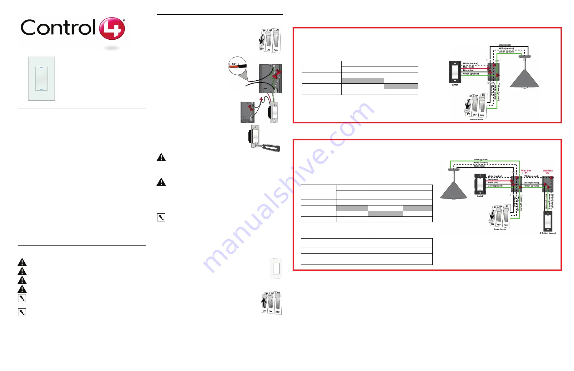
Single-Location Scenario—Power Source at Wall Box
NOTE: This device will not function without a neutral AC connection.
To wire the switch for a Control4 single-location scenario in which the
power is first routed to the wallbox, connect together and cap with a
wire nut the wires indicated in the following table:
Switch Wires
Wires in the Wall Box
From Power Source
To Light Fixture
White (neutral)
White (neutral)
White (neutral)
Red (load)
None
black (load)
Black (hot)
Black (hot)
None
Green (ground)
Green (ground)
Green (ground)
Two-Location Scenario—Power Source at Wall Box
NOTE: This device will not function without a neutral AC connection.
To wire the switch and a multi-button keypad in a two-location scenario
(Control4’s 3-way-switch solution) where the power is first routed to the wall
box, do the following:
1. Wire the switch into Wall Box #1 by connecting together and capping with a
wire nut the following wires:
Switch Wires
Wires in Wall Box 1
From Power
Source
To Light Fixture
To Wall Box
2
White (neutral)
White (neutral)
White (neutral)
White (neutral)
Red (load)
None
Black (load)
None
Black (hot)
Black (hot)
None
Black (traveler)
Green (ground)
Green (ground)
Green (ground)
Green (ground)
2. Wire the multi-button keypad into Wall Box #2 by connecting together and
capping with a wire nut the following wires:
Multi-Button Keypad Wires
Wires in Wall Box 2
(from Wall Box 1)
White (neutral)
White (neutral)
Green (ground)
Green (ground)
Black (traveler)
Black (traveler)