NOTE:
Third-party panels do not require a Terminal Block.
Installation Instructions
Install in a Control4 Panel
1
The 8-Port Ethernet Switch should be installed in the panel next to the 8-Port
Ethernet Switch Terminal Block.
2
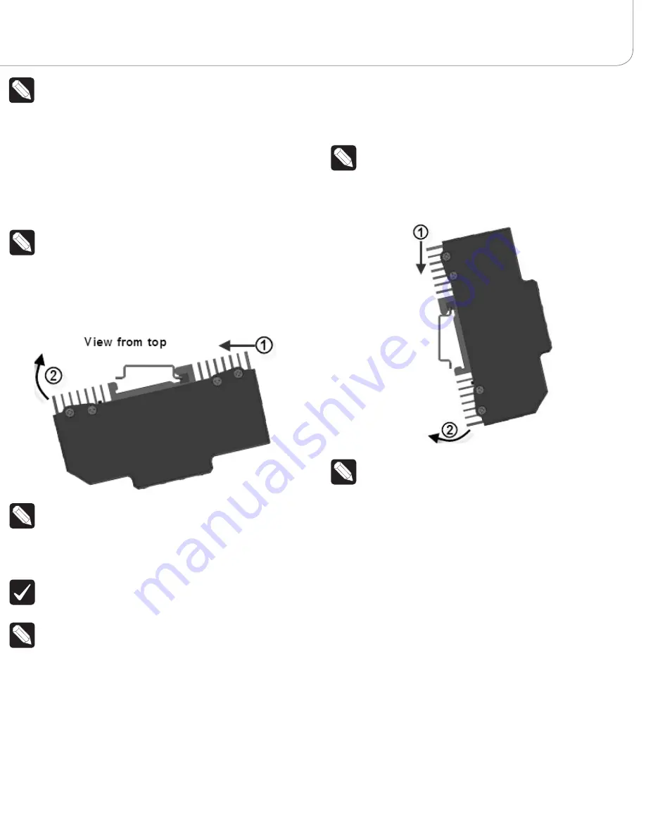
With the green screw terminals on the left side of the 8-Port Ethernet Switch,
hold the switch upright and angle it to the right so that the right side of the
module fits onto the rail in the panel.
NOTE:
The 8-Port Ethernet Switch installs with the Line Voltage
Connector on the left side and the Ethernet ports on the right side. While
not required, the 8-Port Ethernet Switch should be installed in the bottom
slot of the panel.
3
With the right side already in place, push forward on the left side of the
8-Port Ethernet Switch to snap it onto the rail (see Figure 2).
Figure 2. Snap on the Ethernet Switch - Control4 Panels
NOTE
: To remove the module, push the module toward the left side, pull
out from the left side., and remove it from the right side.
4
On the left side of the 8-Port Ethernet Switch, connect the Line, Neutral and
Ground wires from the Terminal Block to the screw terminals on the module
(see the
8-Port Ethernet Switch Wiring Guide
for details).
IMPORTANT!
All wires between the Terminal Block and the Ethernet
Switch must use the same gauge wire as the field wiring connected to the
Terminal Block.
NOTE:
Wiring between the Terminal Blocks and the module will be easiest
when stranded wire is used.
đŏ
At the terminal block side, strip the wires 0.35 in. (9mm) and tighten to
7 in-lb (0.8Nm).
đŏ
At the module side, strip the wires 0.3 in. (7mm) and tighten to 5.3
in-lb (0.6Nm).
5
On the right side of the 8-Port Ethernet Switch, connect the incoming
Ethernet CAT5 cable to an RJ-45 port.
6
Install the other modules in the panel as defined in the reports from
Composer Pro. See the
ĉġ$**!(ŏ%))!.ŏ */0((0%+*ŏ1% !
,
ĉġ$**!(ŏ!(5ŏ
*/0((0%+*ŏ1% !
, or the
ŏĉġ$**!(ŏĀġāĀŏ%))!.ŏ */0((0%+*ŏ1% !
for
details.
7
Connect CAT5 patch cables from the Ethernet Switch to the other modules in
the cabinet.
8
Turn the circuit breakers back ON and test the devices.
Install in a Third-Party Panel
1
With the green screw terminals pointing downward, hold the switch
lengthwise and angle it up so that the top side of the module fits onto the rail
in the panel.
NOTE:
The 8-Port Ethernet Switch installs with the Line Voltage
Connector on the bottom and the Ethernet ports on the top.
2
With the top side seated in the rail, rotate the 8-Port Ethernet Switch down to
snap it onto the rail (see Figure 3).
Figure 3. Snap on the Ethernet Switch - Third-Party Panels
NOTE
: To remove the module, push the module toward the bottom, rotate
the module up, and lift it off.
3
Connect the Line, Neutral and Ground wires to the screw terminals on the
module (see the wiring diagrams in the
8-Port Ethernet Switch Wiring Guide
).
Strip the wires 0.3 in. (7mm) and tighten to 5.3 in-lb (0.6Nm).
4
On the top of the 8-Port Ethernet Switch, connect the incoming Ethernet
CAT5 cable to an RJ-45 port.
5
Install the other modules in the panel. See the
ĉġ$**!(ŏ%))!.ŏ */0((0%+*ŏ
1% !
,
ĉġ$**!(ŏ!(5ŏ */0((0%+*ŏ1% !Čŏ
or
ĉġ$**!(ŏĀġāĀŏ%))!.ŏ
*/0((0%+*ŏ1% !
for details.
6
Connect the CAT5 patch cables from the 8-Port Ethernet Switch to the other
modules in the panel.
7
Turn the circuit breakers back ON and test the devices.
Operation
The recessed Reset button on the front of the module (see Figure 1) can be used
to reboot the Ethernet switch without removing power. Use a paper clip or similar
device to access the Reset button.


