EMM-R3 VA
instruction manual
IM425-U v2.0
pag. 7
TECHNICAL
CHARACTERISTICS
MEASURES, ACCURACY
Voltage
True rms for the phase, phase to phase and three-phase voltage
Total measuring range: 20÷500V trms phase-phase - 290V rms phase-neutral, depending always to the
power supply voltage.
Visualization (0,02÷50,0kV) – measuring accuracy: ±0,5% ±1 digit
Current
True rms for the phase and three-phase currents.
Measuring range: 0,02÷5A trms - accuracy: ±0,5% ±1 digit
Visualization 0,02÷9990A
Frequency
Frequency of the phase L1 – measuring range: 30÷500Hz
accuracy: ±0,5% ±1 digit
AUXILIARY POWER SUPPLY -INPUTS
Aux. power supply
Standard 380-415V ±15% - options 100-125 / 220-240V ±15%
Frequency 50-60Hz - absorption 3VA
Voltage taken from the measuring voltage inputs
Voltage inputs
from 20 to 500V phase-phase (always depending on the auxiliary supply); permanent ov20% -
impedance at the input: 1 M
Ω
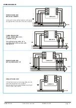
Three-phase wiring with 3 or 4 wires, and single-phase wiring
MV connection through external VT with programmable transformation ratio from 1 to 400
Current inputs
From 0,02 to 5A; permanent overload 30% - from external CT’s with secondary 5A
primary programmable from 5 to 10000A – self consumption <0,5VA
GENERAL
Display and keyboard
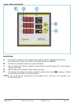
3 display with red LED of 10 mm each, made of 3 digits of 7 segments
2 keys for selection of measures and programming
Mechanical
Protection degree: IP52 frontal - IP20 enclosure and terminals - weight: approx. 0,5 kg.
Wiring through terminals for screws, cross section cable of 2,5 mm
2
Self-extinguishing plastic enclosure –Flush mounting DIN 96x96mm, depth 56mm
Environment Working
temperature:
-10÷60°C; relative humidity <90%
Storage temperature: -25÷70°C
Isolation test: 3 kV during 1 minute
Standards of reference
and Marking
CEI EN 50081-2; CEI EN 61000-6-2;
CEI EN 61010-1
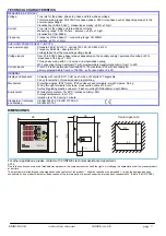
DIMENSIONES
92
92
R3
96
96
90
96
56
9
20
k
M
k
L1
L2
L3
multi meter
Σ
L
V
L-N
A
cos
ϕ
W
VAr
VA
V
L-L
V
L-N
°C
Hz
V
L-L
PEAk
foratura pannello
k
M
k
V
L-L
V
L-N
°C
L1
L2
L3
Σ
L
Hz
electrical
multi meter
V
A
P.F.
W
VAr
VA
V
L-N
L-L
pea
k
L1
L2
L3
Σ
L
V
L-N
V
L-L
A
electrical multi meter
L1-2
L2-3
L3-1
MAX
Hz
k
max
avg
k
For other applications, please contact with CONTREL technical assistance department.
NOTE
Due to the continuous evolution of standards and products, the company reserves itself the rights of modifying the characteristics of the present product,
at any time.
The manufacturer’s liability due to damages caused by defects of the product...” might be reduced or superseded (...) when the damage has been
caused jointly, by a product’s defect or/and by cause of the injured party or a person under the injured party’s responsibility” (Article 8, 85/374/CEE).


