Maintenance and Adjustments
Teledyne Continental Motors, Inc.
TM
9-26
IOF-550 Permold Series Engine Maintenance Manual
1 April 2007
3.
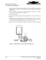
Repeat idle fuel pressure check and adjustment until idle fuel pump pressure
stabilizes at the value specified in Table 9-5. Hand-tighten the relief valve lock nut to
secure it during further testing.
4.
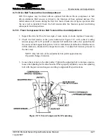
Locate the adjustable orifice on the side of the fuel pump (Figure 9-13).
a.
Turn the screw on the adjustable orifice in one of the following directions, to
obtain a full power fuel pressure indicated in Table 9-5:
1)
Clockwise to increase full power fuel pressure
2)
Counter-clockwise to decrease full power fuel pressure.
5.
After successfully setting the idle and full power fuel pressure, adjust the idle RPM
adjustment on the throttle body (Figure 9-14) to attain a stable 700
±
25 RPM setting.
a.
Clockwise to increase idle speed.
b.
Counter-clockwise to decrease idling speed.
6.
Recheck and adjust the idle fuel pressure, full power fuel pressure, and idle RPM
settings in steps 2-5 until all settings meet the stated specifications.
7.
After the idle fuel pressure, full power fuel pressure, and idle RPM are properly set,
torque the lock nut on the base of the low pressure relief valve and complete one final
check of each setting to verify application of torque to the nut did not alter the setting.
IDLE RPM
ADJUSTMENT
CW = INCREASE
CCW = DECREASE
Figure 9-14.
Idle Speed Adjustment Screw


