background image

November 2011

 72-30-05

A. Connecting Rod Magnetic Particle Inspection

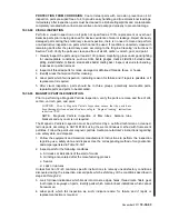
Before performing the Connecting Rod Magnetic Particle Inspection, the connecting rod and 
cap must be clean and free of rust, scale, oil, or other residue that may affect the reliability of 
the Magnetic Particle Inspection. Inspect the connecting rods using both the circular and 
longitudinal method of magnetization. Use the fluorescent method, wet continuous procedure, 
reference ASTM standards for non-destructive testing.

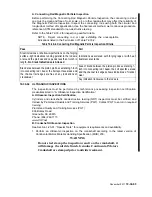
Refer to the Table 72-30-2 for inspection pass/fail criteria.

NOTE... Reject connecting rod or caps exhibiting the unacceptable 
indications listed in the Fail column of Table 72-30-2.

72-30-04

ULTRASONIC INSPECTIONS

The inspections must be performed by technicians possessing inspection certification 
credentials listed in “A. Ultrasonic Inspection Certification.”

A. Ultrasonic Inspection Certification

Cylinders and crankshafts nondestructive testing (NDT) inspectors must be certified and 
trained by Plumstead Quality and Training Services (PQT). Contact PQT to enroll in required 
training:

Plumstead Quality and Training Services (PQT)
806 Botany Road
Greenville, SC 29615
Phone: (864) 292-1115

www.PQT.net
B. Crankshaft Ultrasonic Inspection

See Section 1-20-01, “Special Tools”  for equipment requirements and availability.

1. Perform an Ultrasonic Inspection on the crankshaft according to the latest version of 

Continental Motors Material Handling Specification (MHS) 200.

WARNING

Do not steel stamp the inspection result on the crankshaft, it 
will damage the nitride finish. Genuine Continental Motors 
Crankshaft are stamped prior to nitride treatment.

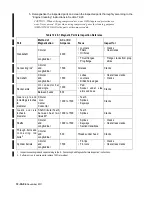
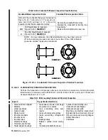
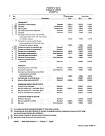
Table 72-30-2. Connecting Rod Magnetic Particle Inspection Criteria

Pass

Fail

Steel inclusions or shallow imperfections on the forging 

surface - light indications running parallel to the rod axis 

or around the pin boss and cap ends less than ½-inch in 

length - No Crack Indications are Allowed

Indications associated with forging laps or with heat 

treatment are cracks

Blend area between the piston pin boss extending 1-inch 

into connecting rod I beam, the bolt spot face areas and 

the channel rail edges are free of any indications of 

cracks/wear

Area of blend between the piston pin boss extending 1-

inch into connecting rod I beam, the bolt spot face areas 

and the channel rail edges shows indications of cracks/

wear
Any indication transverse to the rod axis.

Содержание LTSIO-520-AE

Страница 1: ...blication X30575 CHANGE 6 2011 2012 CONTINENTAL MOTORS INC DEC 2012 TSIO 520 C G H M P R T AE AF CE CONTINENTAL AIRCRAFT ENGINE SANDCAST SERIES ENGINE OVERHAUL MANUAL TECHNICAL CONTENT ACCEPTED BY THE FAA ...

Страница 2: ...8 20 01 thru 78 20 02 3 5 10 01 thru 5 10 02 3 72 30 12 0 72 60 06 0 79 00 01 thru 79 00 04 3 5 20 01 thru 5 20 04 3 72 30 13 thru 72 30 14 3 72 60 07 3 79 10 01 thru 79 10 02 3 5 30 01 thru 5 30 02 3 72 30 15 0 72 60 08 thru 72 60 20 0 79 20 01 thru 79 20 02 3 70 00 01 1 72 30 16 3 72 70 01 thru 72 70 05 0 80 00 01 thru 80 00 10 3 70 00 02 thru 70 00 04 3 72 30 17 0 72 70 06 thru 72 70 07 2 81 00...

Страница 3: ...of the type certificated product on which the part is eligible for installation stamped on the part An FAA Parts Manufacturer Approval FAAlPMA is issued under FAR 21 305 The make and model information may be on a tag attached to the part d By shipping ticket invoice or other document which provides evidence that the part was produced by a manufacturer holding an FAA Approved Production Inspection ...

Страница 4: ...s applicable to proper overhaul procedures Prior to overhaul the mechanic must meet requirements of Federal Aviation Regulation 65 and must follow FAR parts 43 91 and 145 as applicable This manual must be used in conjunction with the FAA Advisory circular 43 13 1A Acceptable Methods Techniques and Practices Aircraft Inspection and Repair as well as Teledyne Continental Motors TS10 520 Sandcast Ser...

Страница 5: ...red in this System Chapter The major System Chapters are then broken down into Sub System Sections These sections are identified by the second element of the standardized numbering system The number 10 of the basic number series 72 10 00 is for the disassembly of the engine The Subsection in the third element of the standardized numbering system 72 10 12 This number is the final breakdown of the C...

Страница 6: ...n of Engine Model Code Basic Design Features TOOLS Special Tools PRODUCTS Product List CHAPTER 4 AIRWORTHINESS LIMITATIONS Airworthiness Limitations CHAPTER 5 TIME LIMITS MAINTENANCE CHECKS GENERAL TIME liMITS INSPECTION PROGRAM SCHEDULED MAINTENANCE Preflight Inspection 50 Hour Inspection 100 Hour Inspection UNSCHEDULED MAINTENANCE CHAPTER 70 STANDARD PRACTICES GENERAL LOCKWIRE PROCEDURE CRANKCAS...

Страница 7: ...eto and Accessory Drive Induction System TSIO 520 C G H M P R AF Induction System TSIO 520 T Induction System TSIO 520 AE Induction System TSIO 520 CE Oil Sump TSIO 520 C G M T on Sump TSIO 520 H P R AE AF CE Oil Cooler Alternator Assembly Starter and Starter Drive Adapter TSIO 520 C G H M P R AF Starter and Starter Drive Adapter TSI0 520 T AE CE Oil Pump Assembly TSIO 520 C G H M P R AF Oil Pump ...

Страница 8: ...ng Replacement Crankshaft Assembly Idler Gear Magneto and Accessory Drive Adapter Assembly Tachometer Drive Housing Starter Drive Adapter Oil Pump Assembly Ignition Cables CHAPTER 72 30 INSPECTION General Visuallnspection Magnetic Particle Injection Crankshaft Ultrasonic Inspection F10urescent Particle Inspection Dimensionallnspection Dimensional Umits Original Dimension New Parts and Service Umit...

Страница 9: ...ssemblies Pushrod Housing Crankshaft and Connecting Rods Camshaft Crankcase Fuel Injection Control and Air Throttle Body CHAPTER 72 60 FINAL ASSEMBLY GeneraL Crankcase Cylinders and Pistons Oil Pump TSIO 520 C G H M P R AF on Pump TSIO 520 AE Oil Pump TSIO 520 T CE Fuel Pump Starter Drive Adapter Alternator Assembly Magneto and Accessory Drive Adapters Oil Cooler Valve Mechanism Oil Sump TSIO 520 ...

Страница 10: ...her Fuel System Governor Pad Cover Engine Test Starting Procedure Overhaul Test Run CHAPTER 72 80 ENGINE PRESERVATION General Flyable Storage Temporary Storage Indefinite Storage CHAPTER 73 00 ENGINE FUEL SYSTEM Engine Fuel System Set up Procedure Turbocharged Engines Fuel Pressure Regulators Special Set up Procedures GENERAL CHAPTER 74 IGNITION TCM IGNITION SYSTEM Magneto Installation Harness Ass...

Страница 11: ...520 T EXHAUST SYSTEM TROUBLESHOOTING CHAPTER 79 OIL GENERAL APPROVED PRODUCTS OIL SYSTEM TROUBLESHOOTING GENERAL Prestarting Starting Ground Warm Up Pre takeoff Check Flooded Engine CHAPTER 80 STARTING Cold Weather Operation Preheating Hot Weather Operation Ground Operating At High Altitude Airports GENERAL Turbocharger Wastegates Controllers CHAPTER 81 TURBINES Turbocharger Lubrication System Tur...

Страница 12: ...Bushing Remover Installer Set Piston Ring Compressors Floating Holder Valve Spring Compressor Push Rod Housing Spring Compressor Flaring Tool Push Rod Housing Valve Guide Remover Valve Seat Insert Remover Replacer Valve Seat Installer Common Parts Kit Valve Guide to Seat Aligner Valve Stem Hole Reamer Boring Bars Reamers Expanding Guide Bodies Valve Seat Insert Cutters RosarfIDStud Remover Connect...

Страница 13: ...ft Oil Seal Installer Oil Pressure Relief Spot Facers Runout Block Set Polishing Tools for Crankshaft Bearings 8087 Series Injector Nozzle Remover and Installer Crankcase Thru Boit Removers Hex Drive for Hex Tube Nuts Rotobroach Cutter Pullers Pullers Pullers Pullers Outside Micrometers Dial Bore Gages Blade Micrometers Screw Thread Micrometers 126 226 Depth Micrometers Reamers Rocker Shaft Suppor...

Страница 14: ... P R AE AF CEo Oil Cooler Starter and Starter Drive Adapter TSI0 520 C G H M P R AF Starter Adapter TSI0 52O T AE CEo Oil Pump Assembly TSI0 520 C G H M P R AF Oil Pump Assembly TSI0 52O T Oil Pump Assembly LjTSI0 52O AE Oil Pump Assembly TSI0 52O CE Cylinder and Piston Assembly All Except LjTSI0 520 AE Cylinder and Piston Assembly LjTSI0 S20 AE Crankcase Assembly Camshaft Assembly Crankshaft Grou...

Страница 15: ...ce Left Side of Complete Crankcase on Stand Installing NO 6 Cylinder Tightening Cylinder Base Nut Cylinder Flange Torque Sequence for Single Cylinder Installation Oil Pump Fuel Pump and Starter Adapter Installed Installing Pushrod Housing Bottom View with Valve Mechanism and Oil Sump Suction Tube Position of Magneto Couplings Ignition Wiring Diagram Exhaust Flange Dimensions Fuel System Schematic ...

Страница 16: ...ydrauliC Une Fittings Fuel Manifold Valve Fitting Locations for TSIO S20 CE Fuel Manifold Valve Fitting Locations for TSIO 520 C G H M P R T AE AF Fuel Control Valve Fitting Locations Fuel Pump Fitting Locations for TSIO S2O t Fuel Pump Fitting Locations for TSIO S20 AE Fuel Pump Fitting Locations for TSIO S2O C G H M P R AF CE Crankcase Assembly Procedure Magneto to Engine Timing Standard Accepta...

Страница 17: ... TITLE Exhaust System Troubleshooting Approved Oil Products Lubrication System Troubleshooting Turbocharging System Troubleshooting Maximum Allowable Manifold Pressure vs Altitude PAGE NO 78 20 01 79 10 01 79 20 01 81 20 01 81 20 02 February 1989 xvii ...

Страница 18: ...xviii February 1989 INTENTIONALLY LEFT BLANK ...

Страница 19: ... Service Documents 1 00 04 Service Reports and Inquiries 1 00 05 100 Replacement Parts 1 10 00 DEFINITIONS ABBREVIATIONS 1 10 01 Abbreviations Symbols 1 10 02 Definitions 1 10 03 Description of Engine Model Code 1 10 04 Basic Design Features 1 20 00 TOOLS 1 20 01 Special Tools 1 30 00 PRODUCTS 1 30 01 Product List ...

Страница 20: ...failure CAUTION Emphasizes certain information or instructions which if disregarded may result in damage to the engine or accessories NOTE Provides special interest information which may facilitate performance of a procedure or operation of equipment Warnings and cautions precede the steps to which they apply notes are placed in the manner which provides the greatest clarity Warnings cautions and ...

Страница 21: ...copy of applicable Service Documents in affected manuals until the service document instructions are incorporated in the manual or the service document is cancelled or superseded Category 1 Mandatory Service Bulletin MSB Used to identify and correct a known or suspected safety hazard which has been incorporated in whole or in part into an Airworthiness Directive AD issued by the FAA or have been i...

Страница 22: ...al service document set but will be made available through our Customer Service Department to owners of the affected engines only An SSI may update the applicable engine s Instructions for Continued Airworthiness 1 00 04 SERVICE REPORTS AND INQUIRIES Continental Motors factory representatives are available to answer technical questions We encourage owner suggestions regarding products parts or ser...

Страница 23: ...ts All engine baffles must be repaired or replaced and all flexible baffle seals replaced Replace items such as spark plugs alternator drive belts and air conditioning drive belts are on condition In addition to the items listed above the following parts must be discarded and replaced with new parts during engine overhaul Bearings connecting rod crankshaft main and thrust needle ball and roller Bu...

Страница 24: ...must be re installed in the location from which they were removed Replace unserviceable hydraulic lifters with new lifters Crankcases for All Models Crankcases candidates for overhaul must have the modifications specified in Service Bulletins M78 9 M90 16 and pass the inspection criteria detailed in in M90 17 ...

Страница 25: ... Center of Gravity Cubic Feet Per Minute Cylinder Head Temperature Counterclockwise Rotation Clockwise Rotation Degrees of Angle Degrees Fahrenheit Exhaust Gas Temperature Figure Illustration Propeller End of Engine Foot or Feet Full Throttle Foot Pounds Torque Gallons Per Minute Grams Hexagon Water Mercury Hour Inside Diameter Inch Pounds Torque Inches Side on which No s 2 4 and 6 cylinders are l...

Страница 26: ... applying a brake to the power shaft of an engine The required effort to brake the engine could be converted to horsepower hence brake horsepower BSFC Brake Specific Fuel Consumption Fuel consumption stated in pounds per hour per brake horsepower For example an engine developing 300 horsepower while burning 150 pounds of fuel per hour has a BSFC of 5 Cavitation Cold Soaking Corrosion Critical Alti...

Страница 27: ...m amount of moisture the air could contain at a given temper ature Inability or restriction of piston rotation at TDC due to fluid accum ulation in excess of combustion chamber displacement A mechanical device used in some magnetos to retard the ignition timing and provide higher voltage at cranking speeds for staring The leanest mixture approved for any given power condition It is not necessarily...

Страница 28: ...00 octane fuel For example an engine with high compression and high temperature needs a higher Performance Rated fuel than a low compression engine A rating of 100 130 denotes performance characteristics of lean 100 and rich 130 mixtures respectively A term used to describe a process by which a crankcase is made An engine with a permold crankcase has a front right hand mounted gear driven alternat...

Страница 29: ...nd axis and the piston pin center would be straight line Ignition and valve timing are stated in terms of degrees before or after TDC Regarding engines the percent of total heat generated which is converted into useful power Turbine Inlet Temperature The measurement of E G T at the turbo charger turbine inlet Twisting moment or leverage stated in pounds foot or pounds inch A device used to supply ...

Страница 30: ...ngines to divert exhaust gas through or around the turbine as necessary to maintain turbine speed As more air is demanded by the engine due to throttle operation the compressor must work harder In order to maintain compressor and turbine speeds more exhaust must be flowed through the turbine The wastegate valve closes and causes gas which would go directly overboard to pass through the turbine The...

Страница 31: ...ion propeller flange A mounting pad is provided to utilize a hydraulic controlled governor for the constant speed propeller The T810 520 series engines are of a wet sump design with a positive displacement oil pump installed on the lower rear portion of the crankcase The desired oil pressure is maintained by a pressure relief valve located in the oil pump housing Engine cranking is accomplished by...

Страница 32: ...THREE QUARTER RIGHT FRONT VIEW OF THE TSI0 520 SANDCAST SERIES ENGINE THREE QUARTER LEFT REAR VIEW OF THE TSI0 520 SANDCAST SERIES ENGINE 1 10 08 February 1989 ...

Страница 33: ...3 56 20 04 7 62 8 20 17 10 H 40 91 33 56 23 54 7 62 8 20 17 10 M 40 91 33 56 20 04 7 62 8 20 17 10 P 40 91 33 56 20 04 7 62 8 20 17 10 R 40 91 33 56 20 04 7 62 8 20 17 10 T 38 20 33 56 28 67 7 62 8 20 17 10 AF 40 91 33 56 26 60 7 62 8 20 17 10 LIT AE 41 00 33 29 21 12 8 15 7 64 14 00 CE 41 00 34 00 25 00 7 62 8 20 17 10 February 1989 1 10 09 ...

Страница 34: ...1 10 10 February 1989 INTENTIONAllY LEFT BLANK ...

Страница 35: ...TOOLS Specific tools illustrated or similar tools marketed by other manufacturers are necessary for service and maintenance of the aircraft engine Tool Hlustratlons shown on the follOWing pages are used with the permiSSion of the respective manufacturers Illustrations In this section show only the general appearance of tools and do not correspond to the actual size or shape Details of special tool...

Страница 36: ...0 507 451 5310 McMASTER CARR SUPPLY CO P O Box 4355 Chicago Illinois 60680 312 833 0300 SNAP ON TOOLS 2611 Commerce Blvd Birmingham Alabama 35210 205 956 1722 Kell Strom Tool Company Inc 214 Church St Wethersfield CT 06109 1 20 02 February 1989 GENERAL PRODUCT SUMMARY Instruments for Ught Powered Aircraft Special Tools Precision Instruments Measuring Instruments Precision Tools Special Tools Spark...

Страница 37: ... FOR TOOLS SUPPUER ALCOR INC BORROUGHS TOOL AND EQUIPMENT CORP CHAMPION SPARK PLUG CO EASTERN ELECTRONICS INC FEDERAL TOOL SUPPLY CO INC OTC TOOLS EQUIPMENT CO McMASTER CARR SUPPLY CO SNAP ON TOOLS KELL STROM TOOL COMPANY INC Numbers referenced in the left hand bottom comer of each picture correspond to the numbers located in the Special Tool Index WARNING Whenever using test equipment keep equipm...

Страница 38: ...ing Fixture Cylinder Hold Down BTC 11 122 Valve Guide Cleaner Cylinder Reconditioning BTC 12 8066 Seal Seat Cutter Cylinder Reconditioning BTC 13 7521A Spring Checker Spring Inspection BTC 14 3611 Valve Guide Remover Cylinder Reconditioning BTC 2874 Valve Guide Remover Cylinder Reconditioning BTC 15 4912 Valve Guide Replacer Cylinder Reconditioning BTC 3619 Valve Guide Replacer Cylinder Reconditio...

Страница 39: ...1A Connecting Rod Fixture Connecting Rod Inspection BTC 35 8042C Adapter Kit Connecting Rod Inspection BTC 36 874 40 41 Reamers Conrod Bushing Connecting Rod Reconditioning BTC 5008 8071 Reamers Conrod Bushing Connecting Rod Reconditioning BTC 37 8098 Remover Installer Set Connecting Rod Reconditioning BTC Connecting Rod Bushing 38 8122A Common Drive Handle Cylinder Reconditioning BTC 8139 40 41 P...

Страница 40: ... Crankcase Spitter Crankcase Separation BTC 71 5209 Propeller Shaft Oil Seal Installation of seal over Propflange BTC Installer 72 8048 Oil Pressure Relief Spot Removal of surface Material around BTC Facer holes 8155 Oil Pressure Relief Spot Removal of surface Material around BTC Facer holes 73 8117A Runout Block Set Crankshaft Inspection BTC 74 8087A B Polishing Tools for Crank Crankshaft Recondi...

Страница 41: ...mer Square Shank Cylinder Reconditioning BTC 2686 Reamer Square Shank Cylinder Reconditioning BTC 2689 Reamer Square Shank Cylinder Reconditioning BTC 2693 Reamer Square Shank Cylinder Reconditioning BTC 4104 Reamer Square Shank Cylinder Reconditioning BTC 92 2848 1 Plug Gage Valve Guide Inspection BTC 2848 2 Plug Gage Valve Guide Inspection BTC 3615 Plug Gage Valve Guide Inspection BTC 93 7308 Di...

Страница 42: ...from the engine and place on a drain tray Allow oil to drain through a clean cloth to determine if foreign material drains from the filter 2 Using the Champion CT 470 Can Cutter open the filter as follows See photos 1 20 08 February 1989 Oil Filter Can Cutter CT 470 o a Insert threaded adapter in female threads of filter or screw rotating bushing on male threads of filter b Slightly tighten cutter...

Страница 43: ... 9 16 hex 3882 3A 5 8 hex 3882 3 5 8 hex 3882 4 3 4 hex Cylinder Base NutWrench Special modified 3882 type wrench this special wrench is perfect for those occasional situations when the 3882 wrench won t fit It s a slightly different configuration as shown 80799 16 hex Cylinder Base Nut Wrench For 470 and 520 Series The special configuration of these wrenches permits access to the cylinder base nu...

Страница 44: ...r size with universal joint action Optional set for use on TCM cylinders CFL10 Standard 3 to 4 1 4 CFL10 7 Optional 4 to 6 1 2 Crankshaft Blade and Dampener Bushing Removers Replacers Back up plates and forcing screws are rugged heat treated alloy steel Be sure to keep forcing screws greased 4965A 3604 3607 3607 1 8068 for 5 8 1 0 Bushing for 3 4 1 0 Bushing for 15 32 1 0 Bushing for GTSIO 520 for...

Страница 45: ...adapters Universal Cylinder Holding Fixture 5221 B This is a heavy duty precision fIXture manu factured to extremely close tolerances Suitable for use on vertical mills or drill presses it allows quick indexing of required angles for valve work FEATURES For all Continental Engines Fixture indexes in all present positions required to machine valve guides Locks in at these angles Adapter rings are i...

Страница 46: ...pring Checker 7521A Per Continental Bulletin M74 16 Check valve spring quickly and easily Hy draulically actuated extremely accurate readout 0 160 pounds Includes step gauges for all required dimensions 7521 Checker is less step gauges Max spring dimensions Ht 2 1 2 0 0 2 Heat Shrink Type Valve Guide Removers Cold Force Removal Type Tough heat treated steel 3611 375 1 0 Guide 2874 436 438 1 0 Guid...

Страница 47: ...pter Assemblies also available individually The 8098 10 Base must be used with 81100 811H 8118J and 8118K Driver and Adapter Assemblies Makes rocker arm bushing removal installation fast and easy All components of 8118 set are also available individually Piston Ring Compressors Flexible Band Type 4901 for 3 7 8 and 4 1 6 bore engines 2839 for 5 and 5 1 4 bore engines 3618 for 4 7 16 bore engines T...

Страница 48: ...ring loaded tubes The 68 3 compresses the spring which can then be removed with furnished clips Eliminates wiring springs together to install simply Insert spring then pull off clip Includes instructions Flaring Tool for Push Rod Housing 4951A For A C Series expanding ball type tool Balls rotate inside housing expanding it into aluminum boss Valve Guide Remover 4981 Removes guides by heat shrink m...

Страница 49: ...ncludes 1 Handle lever assembly 12 Puller heads size to fit all Continental engines 10 Installer pilots 1 Remover plug 6 feet of super flexible hose to attach to water supply Instructions Storage case Tool is rigged for removal Center is plugged to route water out thru small holes in rim of removing head Fig 1 Installer Valve Seat Inserts 4910 For 1 45 64 0 0 Exhaust and 1 53 64 0 0 Intake Inserts...

Страница 50: ...ATS AND GUIDES CAN BE RE ALIGNED QUICKLY Here s how H s done Step 1 Removed old guides and seats Step 2 Install Expanding Guide Body into va ve seat boss Step 3 Place Boring Bar into Guide Bore valve guide boss concentric and perpendicular to va ve seat Follow up with Reamer Step 4 Use your drill press for bore or ream operations as shown in this picture The same guide set up works for both 1 20 1...

Страница 51: ... Dia 8116 18 525 8116 28 530 8116 38 535 8116 48 540 8116 58 545 8115 68 555 8116 108 620 8116 118 625 8116 128 630 8116 138 635 8116 148 640 8116 158 650 Example Use 8116 68 Boring Bar to bore hole to 555 then finish with 8116 6R Reamer to 561 dia Expanding Minimum Maximum Body No Retracted Dia Expanded Dia 8116 1 1 656 1 681 Expanding 8116 2 1 685 1 710 Guide 8116 3 1 748 1 773 Bodies 8116 4 1 7...

Страница 52: ... 125 015 5225 30 Exh 1 818 030 4985 4 Int 2 130 020 Rosan Stud Remover This stud remover is for use in extracting studs from cylinder assemblies using Rosan type Studs Using the hammer drive the stud driver 1 over stud 2 as far as possible without making contact with the cylinder head 3 Using the ratchet or pull handle apply a firm constant pressure in the clockwise tightening direction the serrat...

Страница 53: ... a dial indicator reading in ten thou sandths of an inch 0001 The gauge body is lapped into the mating bushing for accurate readings Instructions are included Adapter Kits 8042C for 520 470 E Series 8072C for 0 200 0 300 360 1 125 1 00 922 Reamers Connecting Rod Bushing High speed steel reamers with 3 4 diameter pilot Use with 8111A Base Retainer Kit and proper Adapter Kit as shown above 874 40 87...

Страница 54: ...he proper pilot from below you may choose to pilot into valve stem hole or valve guide boss Pilots All pilots are hardened and precision ground for accuracy Two choices pilot into valve stem hole or valve guide boss Pilot Choice No 1 Pilot Into Valve Stem Hole On new Inatallationa only Part No 8139 8410 8141 Pilot Dia 343 374 435 CAUTIO OO NOT USE ON WORN GUIDES 1 20 20 February 1989 8098 10 Base ...

Страница 55: ...nce the bushing Is removed or installed a tum of the valve returns actuator for another cycle B077A includes 10 000 p s l pump and cylinder 5 ton output cylinder 3 ft long flex hydraulic hose all adapters to fit 0 300 and 360 470 and 520 Series 80778 Oess hydraulics includes Items shown above in SOnA except no hydraulics are furnished The actuator head has 1 4 NPT female port for connecting to you...

Страница 56: ...rotates 3600 and locks in place with heat treated lock pin Range holder is pre drilled to accept all Con tinental engines Threaded adapters Included to mount non flanged crankshafts Shipping weight 400 Ibs Tork Band Tension Adjuster 7726 Adjust belt tension without damage to compo nents Use on alternators compressors etc Allows grabbing difficult round components Generator Drive Holder Hold drive ...

Страница 57: ...or 2 Controls 1 Y Connector 1 Stand 2 Cylinder Risers All screws nuts and washers needed instructions and f Blind Needle Bearing 8093C Puller Use to remove 5 8 1 0 needle bearings in 470 and 520 Series engines Use with 8054 Slide Hammer Starter Clutch Shaft Bearing Pullers 80930 for removing 3 4 1 0 bearings Cylinder Risers Controls 36 Hoses JI I ff Y Connector wlfittings Regulator Standard 20 lb ...

Страница 58: ... belt and bearing life The proper belt tension eliminates slippage and increases efficiency of belt driven opponents Compact only 3 1 4 wide to fit in crowded areas Easy to use just apply gauge to belt release ball handle and read tension on rotating dial Calibrated for A section V belts 3 8 to 1 2 top width and K section 4 5 and 6 rib poly V belts Range 30 to 180 Ibs and 130 to 800 newtons dual s...

Страница 59: ...Two point hook up field term and cigarette lighter Engine Timing Disc 3608A For all engines universal application from J3 to DC3 Fastens to prop tip and accurate to 1 4 degree Includes piston stop 360SA 15 Pulley Holder 4974 For holding 2 1 2 to 3 1 2 dia pulleys grip in pulley groove Pulley Alignment Gage Bar 8082 The 8OS2 gage bar allows a quick and easy alignment check between driver sheave and...

Страница 60: ...avy steel wall 0 30 in Hg nozzle fits several sizes of tubing Generator Pulley Puller 61 5 Quick removes pulleys from 2 1 2 to 5 diameter Applies even pressure on outside of pulley in pulley groove All components are tough heat treated alloy steel Bearing and Bushing 8094B Drill Fixture Per Continental Bulletin 79 10 Use to reqork your present stock of main journal bearings and starter shaft bushi...

Страница 61: ...inserting improved thru bolt with 0 ring seal Spark Plug InsertTap 504 1 Use on all engines Spark Plug Insert Remover 4919 Use on all engines Slide Hammer 8054 Heavy duty slide hammer features 2 1 2 lb slide and 5 8 18 thread 24 long overall Use with 8114 Series removers Spark Plug Tap 445 18 millimeter threads High speed steel 8064 Cutter 480 dia 8065 Cutter 500 dia February 1989 1 20 27 ...

Страница 62: ...h pre set stops To modify 470 Scavenge Pump per Continental Bulletin M72 8 Drill Fixture 8025 For drilling and installing piston oil squirt nozzles in 0 470V engines converting to 0 470VO per Continental Bulletin M75 13 10 470 to 10 4700S Includes all drills drill bushings and stops required to a fast and efficient job Crankcase Splitter Set L423 Makes splitting Continental crankcases easier and f...

Страница 63: ...removal Cutter blades are heat treated highspeed steel 8048 Spot Facer for 470 and 520 Runout Block Set 8177A Use this set to check runout on crankshafts etc up to 4 diameter Blocks are aluminum alloy with Teflon bearing surfaces Approx size 4 w x S 1x 5 h each Polishing Tools for Crankshafts Bearings Special aluminum frame and felt polishing surfaces 8087A 1 7 S t02 1 4 dia 80878 2 1 4 to 2 5 S d...

Страница 64: ... durability Torque input and output is marked on extension Installer is special thin walled 6 pt 1 2 hex socket Crankcase Thru Bolt Removers Use with 8054 Slide Hammer to remove stubborn bolts 8114 8 8114 7 8114 6 Remover 1 2 20 threads Remover 7 16 20 threads Remover 3 8 24 threads Hex Drive for Hex Tube Nut 7912A Tubing nut wrench set for fuel systems hydraulic systems and brakes Rotabroach Cutt...

Страница 65: ...1153 Pullers These pullers provide a more controlled method to remove press fit parts 679 d03S o o 1079 927 1063 February 1989 1w 20 31 ...

Страница 66: ...les to outside edges Dial Bore Gages Dial Bore Gages used for large volume go na go inspections or for determination of actual dimensions Three point contact two guide pins and one interchangeable rod assure alignment within bore Zero point may be set with ring gage micrometer height master or gage blocks NOTE All precision measuring devices must have a current calibration that is traceable to the...

Страница 67: ...il Type 60 degree V Anvil and Conical Spindle are made of high grade special steel hardened and precision ground Depth Micrometers The Depth Micrometer is one of the basic measuring tools selected by machinists Rachet stop for consistent and repetitive measurements NOTE All precIsion measuring devices must have a current calibration that is traceable to the National Bureau of Standards 122 125 159...

Страница 68: ...786 Pilot 5129 4 818 Finishing Use with 5129 1 5129 3 815 Pilot 5129 5 833 Finishing Use with 5129 1 5129 2 5129 3 5129 4 815 Pilot Reamer Rocker Shaft Bushing 5130 751 Std 707 Pilot Reamer Rocker Arm Bushing 7232 751 Std 732 Pilot H Reamers Valve Guide Boss Use at 275 RPM maximum USE MORSE ADAPTER 4914 1HS 537 005 O S 531 Pilot ______ 2689 4914 2HS 542 ______ 010 O S 534 Pilot 2689 4914 3HS 552 _...

Страница 69: ... are used to check for new limits and service limits where applicable Gauges are heat treated alloy steel precision ground 2848 1 2848 2 3615 436 1 0 Guide 438 1 0 Guide 375 1 0 Guide USE MORSE CUTTING PILOT ADAPTER DIA 438 344 344 375 438 436 DIA NO 422 2686 331 2684 331 2684 363 2684 422 2686 422 2686 Suggestions For Reaming Valve Guide Stem Holes 1 Use high quality cLitting oil 2 Reamers are ma...

Страница 70: ...nd Metric Measure Inside Measuring Instruments Three measuring surfaces are lapped parallel to the longitudinal axis of the Micrometer and stay aligned with the bore while measurements are taken Large ratchet stop provides constant measuring pressure to the wall surface and insures repet itive reading to 0002 or 0001 smaller ranges NOTE All precision measuring devices must have a current calibrati...

Страница 71: ...ernators regulators batteries on 12 and 24 volt systems with currents up to 32 volts DC Has a pointer zero adjustment screw on the face of the instrument Circuitry is entirely solid state and no battery or power source is required Power for the unit is derived from the systems under test Multiple Voltage Circuit Tester For 12 24 Volts Model 29 Designed to test continuity of circuits shorts diodes ...

Страница 72: ...l E25 Improves the accuracy and speeds up the process of timing an aircraft magneto to the engine Easily attached to the propeller spinner with mounting bands Has top dead center locator ColdCylinder Test Model E10 Attach one wire with an alligator clamp and use another cable with a hand held probe to test comparative temperatures from cylinder to cylinder in a matter of seconds Spot source of rou...

Страница 73: ...lses test insulation for leak Built in continuity lamp provides handy test of electrical connections Uses two c cell flashlight batteries Includes top grain cowhide carrying case Master Orifice Tool PIN 646953 Attach to differential cylinder pressure tester to check calibration and determine the low leakage limit Ref reM Service bulletin M84 15 February 1989 1 20 39 ...

Страница 74: ...unit with a disposable battery Temperature Range 1000o 1800oF Alcor Portable Digital CHT Unit This device is used with Type J Thermocouple It is a lightweight 9 volt LCD unit with disposable battery Temperature Range 200 600 F Indication from 32 6QOoF WARNING Keep equipment and personnel clear of prop area 1 20 40 February 1989 Part Number 85328 Part Number 85329 ...

Страница 75: ...Gear and Pin See GTSIO 520 Remarks 10 TSIO 520 10 TSIO O 470 Fuel Injection Controls See Except Models O rings Springs Shafts and Remarks TSIO 520 D Bushings GTSIO 520 K All 360 Which use Grade 50 MHS 27 Oil Oil Pump pressure All Coat Gear Cavity at scavenge Models Assyof Pump 2 Oil Grade 50 MHS 27 Crankshaft Bearings CITGO Inc Connecting Rod Bearings Prop Driver Driven Gears All _ _ and Bearings ...

Страница 76: ...rquing All Class 4 Studs Plug Vernatherm 4 MIL S 3545 C Grease All Fuel Injection Linkage Shell 5 O Rings on Fuel Pumps All Models At Assembly TaEDVNE CONTINENTALMOTORS Mixture Shaft Bushing AIrcraft Products 5 Alvania Oil Seal Lips Only All Models Shell 2 6 Permatex Aviation Crankcase Parting Face 0 200 C90 0 300 Grade 3D see figure 70 20 00 for Permatex Inc Crankcase Threading Pro and cedure 641...

Страница 77: ... Deck Stud Nuts All Thru Bolts 10 642188 1 Gasket Sealant All Gaskets Both Sides Ex See Tiara 6 285 6 320 TCM cept Magneto Gasket Remarks 1 5 oz tube TEl Et1fNE CONTJNENTALMOTORS Rocker Cover Gaskets See For All Stamped AIrcraft Products cover side Remarks Covers Gasket Accessory Case to See Models C 90 0 200 Crankcase crankcase side Remarks 0 300 AII360 only Gasket Idler Pin See Remarks Models 47...

Страница 78: ...le All Models _ _ _ TE1 EO t NE Engine Mount Studs See 360 Models CONTJNENW MOTORS AIrcraft Products Class 3 Studs in Accessory Remarks Cover Oil Pump Gear Mounting See 360 Models Pin in Accessory Case Remarks Intake Manifold Mount See C75 C85 C90 and Studs Remarks 0 200 All Press Fit Breatherand Oil See 360 Models Filler Necks Remarks VTC Unit Bushing Retaining See Tiara Screw Remarks VTC Unit Ho...

Страница 79: ...ake Manifold Hoses and All Models _ Mold Release Flex Ducts RELEASEAGEN INC 19 Oil Grade 50 MHS 27 Cylinder Studs and Thru All Models Lube Threads Before Bolts Tightening Nuts 20 MIL L 46002 Engines for Temporary All Models Use After Test Oil Preservative Storage Or Indefinite Daubert Chemical Inc Storage Or Pennsylvania Refining Co 21 TCM PIN 626531 1 High Temp Paint for All Models 72 30 13 Ename...

Страница 80: ...1 30 06 February 1989 INTENTIONALLY LEFT BLANK ...

Страница 81: ...CHAPTER 4 AIRWORTHINESS LIMITATIONS February 1989 4 00 01 ...

Страница 82: ...4 00 02 February 1989 INTENTIONALLY LEFT BLANK ...

Страница 83: ...nd 100 hour inspections as described in the TSIO 520 Sandcast Series Overhaul Manual and inspections mandated by the FAA under 43 and 91 of the Federal Aviation Regulations are required for type certification 3 Other Related Procedures Subject to additional information contained in FAA Approved Mandatory Service Bulletins issued after the date of certification the TSIO S20 engines does not have an...

Страница 84: ...4 00 04 February 1989 INTENTIONALLY LEFT BLANK ...

Страница 85: ... 5 20 02 5 20 03 5 30 00 CHAPTER 5 TIME LIMITS MAINTENANCE CHECKS GENERAL TIME LIMITS INSPECTION PROGRAM SCHEDULED MAINTENANCE Preflight Inspection 50 Hour Inspection 100 Hour Inspection UNSCHEDULED MAINTENANCE February 1989 5 00 01 ...

Страница 86: ...5 00 02 February 1989 INTENTIONALLY LEFT BLANK ...

Страница 87: ...guide to assist the owner or operator in meeting their responsibilities This inspection guide is not intended to be all inclusive no guide can replace the good judgement of a certified airframe and power plant mechanic in the performance of his duties As the one primarily responsible for the air worthiness of the airplane the owner or operator should select only qualified personnel to maintain the...

Страница 88: ...5 00 04 February 1989 INTENTIONALLY LEFT BLANK ...

Страница 89: ...e eligible for the TBO increase 1600 hours by installing cylinder valve assemblies PIN 646657A1 piston PIN 648033 ring set P N 642602A2 valve lifters PIN 6462n in both intake and exhaust positions throttle body PIN 649185A1 pressurized magneto kit EQ6583 oil pump assembly PIN 643717 1 PIN 643749 oil pump gasket and oil filter PIN 643227 or Cessna supplied oil filter adapter and associated parts To...

Страница 90: ...5 10 02 February 1989 INTENTIONALLY LEFT BLANK ...

Страница 91: ...agneto Filter 9 Visual 10 Exhaust System 11 Adjustments Repairs 12 Engine Condhion 5 20 03 100 HOUR INSPECTION Replace filter inspect cartridge Change oil if integral screen or small filter is used Inspect and clean or replace as necessary Clean Fuel Nozzles As Required Inspect for chafing and deterioration Check and adjust only if non conformities were noted in Step 1 Inspect for color if white o...

Страница 92: ...OTE Minor changes in magneto timing can be expected during normal engine service The time and effort required to check and adjust the magnetos to specifications is slight and the operator will be rewarded with longer contact point and spark plug life smoother engine operation and less corrective maintenance between routine inspections NOTE At each 500 hours the magnetos should be disassembled and ...

Страница 93: ...rect positioning Inspect and lubricate Pressure check system Check for condition and leaks Pay particular attention to heater muffs Refer to airframe manufacturer for further instructions Check freedom of rotation Check operation and condition Perform service as required on any items that are not within specifictions Perform complete run up Check engine for fuel or oil leaks before returning to se...

Страница 94: ...INTENTIONALLY LEFT BLANK 5 20 04 February 1989 ...

Страница 95: ...ed maintenance of the categories listed above should be attempted without consulting the applicable related publications NOTE In case of engine overspeed refer to the current Overspeed Umitations Service Bulletins NOTE In case of engine overboost refer to the current Overboost of Turbocharged Engines Service Bulletins NOTE Refer to this manual or applicable service bulletins for proper procedures ...

Страница 96: ...5 30 02 February 1989 INTENTIONALLY LEFT BLANK ...

Страница 97: ... 00 LOCKWIRE PROCEDURE I70 20 00 CRANKCASE THREADING PROCEDURE 70 30 00 APPLICATION OF ADHESIVES 70 40 00 INSTALLATION OF GASKETS 70 50 00 CYLINDER LEAKAGE CHECK 70 50 01 Leakage Checks 70 50 02 Equipment 70 50 03 Performing The Check JULY 1987 70 00 01 ...

Страница 98: ...70 00 02 February 1989 INTENTIONALLY LEFT BLANK ...

Страница 99: ...ends If anything is dropped into the engine work should be stopped immediately and the item removed even if considerable time and labor is required Insure all parts are thoroughly clean before assembling especially during engine build up All lockwire and cotter pins must fit into a recess of the nut with the other end bent such that one leg is back over the stud and the other is down flat against ...

Страница 100: ...70 0 04 February 1989 INTENTIONALLY LEFT BLANK ...

Страница 101: ...WIRE HOLES PARALLEL 2 INSERTING WIRE 3 BENDING WIRE AROUND BOLT 4 TWISTING WIRE 5 PULLING WIRE 6 BENDING WIRE AROUND BOLT 7 TWISTING WIRE 8 BENDING TWISTED WIRE 9 CUTTING EXCESS WIRE a Steps in applying safety wire b Typical safety wire patterns February 1989 70 10 01 ...

Страница 102: ...70 10 02 February 1989 INTENTIONALLY LEFT BLANK ...

Страница 103: ...k thread PIN 641543 as shown in illustration being sure that free ends are covered by gaskets except at oil seal NOTE Applying thread to L H 2 4 6 side crankcase half may allow case halves to be assembled easier due to gravity holding governor gear in place Apply silk thread only in areas illustrated 5 Assemble crankcase halves using bolts for alignment to prevent movement of the thread and torque...

Страница 104: ...70 20 02 February 1989 INTENTIONALLY LEFT BLANK ...

Страница 105: ...ubricants Gasket Maker is an easily workable tacky gel which can be extruded onto one side of a flange surface from a tube and evenly spread or small parts can be covered adequately by pressing them into a saturated polyester urethane sponge or by roll coating them with a short pan roUer Once Gasket Maker has been applied evenly torque assembly into place Excess material can be cleaned by wiping c...

Страница 106: ...70 30 02 February 1989 INTENTIONALLY LEFT BLANK ...

Страница 107: ...ket surfaces must be clean and free of oils and grit Apply a thin coat of rCM Copper Coat 642188 to both sides of gasket unless otherwise specified Refer to Item No 10 in Chapter 1 Sealants and Lubricants for application of Copper Coat Once Copper Coat has been applied position gasket with the Copper Coat to its respective side according to Chapter 1 Sealants and Lubricants Evenly torque assembly ...

Страница 108: ...70 40 02 February 1989 INTENTIONALLY LEFT BLANK ...

Страница 109: ...ge check results caused by improper use of test equipment and or by the use of faulty test eqUipment To help you accurately accomplish a leakage check we submit the following information on leakage and use of the Master Orifice tool Ref Figure 70 50 01 to calibrate the leakage checking equipment used on Teledyne Continental engines y FACTORY CALIBRATED ORIFICE Clean with soft brush Do Not Alter Si...

Страница 110: ...al Ref Figure 70 50 02 This seal leakage can vary from engine to engine by the cylinder displacement cylinder choke ring end gap and piston design 70 50 02 EQUIPMENT Testing equipment must be kept clean and checked periodically for accuracy as follows Using a line pressure of 100 to 120 p s i close the cylinder pressure valve then set the regulator pressure valve to 80 p s i The pressure in both g...

Страница 111: ...al pressure tester is shown in Figure 70 50 03 COMPRESSED AIR SOURCE f HAND TIGHT REGULATOR PRESSURE GUAGE REGULATOR PRESSURE VALVE COMPRESSED AIR SOURCE FIGURE 70 50 03 DIFFERENTIAL PRESSURE TESTER CYLINDER ADAPTER 70 50 03 PERFORMING THE CHECK The following procedures are listed to outline the principles involved and are intended to supplement the manufacturer s instructions for the particular t...

Страница 112: ...at the exhaust or induction system cylinder port When checking for cylinder head to barrel leakage use a soapy solution between the fins and watch for bubbles Use a soapy solution also around both spark plug seals for leakage NO LEAKAGE IS ALLOWED IN STATIC SEALS h If leakage is occurring in the intake or exhaust valve areas it may be possible to correct a low reading by staking the valves This is...

Страница 113: ...pressure to 20 p s i and working piston through TDC several times bringing the piston to TOC in the normal direction of engine rotation Adjust regulated pressure to 80 p s i and determine amount of loss If the gage reading is higher than the previously determined master orifice calibrated reading proceed to next cylinder to be tested NOTE Piston ring rotation within the ring land is a normal desig...

Страница 114: ...ug 2 Apply Soapy Loose Heli coll Replace Hell coil Reinspect NO LEAKAGE Solution Around PERMISSIBLE to Port Seal Spark Plug Cracked Cylinder Replace CylInder Cylinder Head Apply Soapy Solu tion Between Bubbles Replace Cylinder to Barrel Seal Head and Barrel Cylinder Head Apply Soapy Solution Around Bubbles Replace Cylinder Cracks Fins SECOND CHECK CHECK FOR METHOD 1 DISCREPANCY 2 CORRECTIVE 2 CORR...

Страница 115: ...09 72 00 10 72 00 11 72 00 12 72 00 13 72 00 14 CHAPTER 72 ENGINE RECIPROCATING GENERAL Introduction Crankcase Crankshaft Connecting Rods Camshaft Pistons Lifters Cylinders Gear Train Lubrication System Valve Mechanism Induction System Exhaust System Ignition System February 1989 72 00 01 ...

Страница 116: ...72 00 02 February 1989 INTENTI0 NALlY LEFT BLANK ...

Страница 117: ...rd AS234 element or equivalent installed in bQss in bottom of cylinder head 7 5 1 1 6 3 2 5 4 4600 F Number of Cylinders 6 Numbering Accessory toward propeller end Right Side Cylinders Left Side Cylinders Bore Inches Stroke Inches Piston Displacement cu in TOTAL BASIC ENGINE WEIGHT DRY No oil in sump Subject to product variation of 2 5 Complete Engine Includes TSIO 520 C TSIO 520 G TSIO 520 H TSIO...

Страница 118: ...Maximum Continuous Recommended Continuous Max for Cruising Fuel Control System Unmetered Fuel Pressure P S I G Fuel Min Grade See Performance Chart Chapter 76 See Performance Chart Continental Continuous Flow Injector See Operating Limits 77 00 01 Aviation Grade 100 or 100LL WARNING The use of a lower octane rated fuel can result in destruction of an engine the first time high power is applied Thi...

Страница 119: ...C 75 F 110 C 240 F 71 82 C 1600F 1800F LEFT 200 10 220 10 200 10 220 10 220 00_10 220 10 220 10 200 10 220 10 200 10 The following magnetos equipped with an appropriate harness are eligible on these engines at the indicated weight change One each TCM S6RN 201 and S6RN 205 One each TCM S6RN 1201 and S6RN 1205 Two TCM S6RN 25 Two Slick Electro Model 662 or 680 Two TCM S6RN 1225 Two Slick Electro Mod...

Страница 120: ...t crankcase and right Crankcase throughout this publication A Bosses molded in the crankcase castings are line bored in the assembled castings to form bearings for the camshaft and seats for precision steel backed lead alloy lined crankshaft main bearing inserts Guides are bored through lateral bosses for tappets and for the governor drive shaft A needle bearing is pressed into the right crankcase...

Страница 121: ...ated on the crankshaft 2 cheek 2 counter weight configuration and on the 2 and 5 cheeks 4 counterweight configuration Where sixth order counterweights are used they should always be installed on the 2 cheek In the case of a crankshaft having 2 counterweights one 4 1 2 order and one 6th order they should be installed on the 2 cheek opposite each other It makes no difference on which side they are i...

Страница 122: ...e installed before the head is screwed and shrunk onto an externally finned steel alloy barrel to make the permanent head and barrel assembly Special 18mm helical coil thread inserts are installed in upper and lower spark plug holes Smaller helical coils are installed in intake manifold attaching bolt holes Both the intake and the exhaust ports are on the bottom of the head when the cylinder is in...

Страница 123: ...kshaft 2 is transmitted by the crankshaft gear 1 directly to the idler gear 14 and camshaft gear 3 C The idler gear rotating in a counterclockwise direction drives magneto drive gears 16 and 17 Optional accessories mounted on crankcase upper rear are driven by internal splines of magneto drive gears D The fuel pump drive gear 25 is driven by the camshaft cluster gear 3 The splined end of the oil p...

Страница 124: ...Tachometer Shaftgear 12 Scavenge Pump Driven Gear 13 Scavenge Pump Driver Gear 14 Idler Gear Assembly 15 Idler Gear Support Pin 16 Left Magneto Drive Gear 17 Right Magneto Drive Gear 18 Starter 19 Worm Drive Shaft 20 Worm Shaft Spring 21 Starter Worm Gear 22 Starter Worm Wheel 23 Clutch Spring 24 Starter Shaftgear 25 Fuel Pump Drive Gear 72 00 10 February 1989 1 1 1 1 0 5 1 0 5 1 0 5 1 1 1 0 5 1 0...

Страница 125: ...cavity oil is directed to the camshaft passage A groove around the front of the camshaft directs oil to the front camshaft bearing and left crankcase oil gallery C Lubricating oil is directed to the governor drive bearing and propeller governor through passages off the left oil gallery Oil is channeled through a discharge port to the crankshaft oil transfer collar which directs it to the crankshaf...

Страница 126: ... LIFTER WASTEGATE CONTROllER OIL PRESSURE BY PASS VAl VE OIL SUCTION _ _ _ OIL THRU RELIEF VALVE OIL THRU OIL TEMI ERATURE COIIIITItOL VALVE OIL UNOER PREaJIIE OIL FROM GOVERNOR FIGURE 72 00 10 LUBRICATION SYSTEM 72 00 12 February 1989 ...

Страница 127: ...ld from reservoir 15 by check valve ball 5 which is supported by a spring 4 and retainer 3 The check valve is opened by outward motion of the plunger under pressure of the expanding spring whenever a clearance occurs in the valve train Thus the body reservoir is kept full of oil which transmits lifting force from the body of plunger The plunger and socket are selectively fitted to the body to perm...

Страница 128: ...e upper spark plugs of the right side cylinders and lower spark plugs of the left side cylinders by a magneto mounted on the right side of the crankcase An identical magneto mounted on the left side of the crankcase produces the current for the upper spark plugs of the left side cylinders and lower spark plugs of the right side cylinders The high tension cables pass through braided flexible shield...

Страница 129: ... 14 NOTE Engine kickback while cranking may cause damage to the engine and is an indication of malfunctioning magneto retard system impulse couplings or retard breaker system not functioning properly 3 1 Magneto 2 T fitting 3 Hose 4 Harness 5 Clamps 6 Filter 7 Elbow 1 FIGURE 72 00 14 PRESSURIZED MAGNETO INSTALLATION February 1989 72 00 15 ...

Страница 130: ...72 00 16 February 1989 INTENTIONALLY LEFT BLANK ...

Страница 131: ...6 Fuel Injection System 72 10 07 Magneto and Accessory Drives 72 10 08 Induction System 72 10 09 Oil Sump 72 10 10 Oil Cooler 72 10 11 Alternator Assembly 72 10 12 Starter and Starter Drive Adapter 72 10 13 Oil Pump Assembly 72 10 14 Cylinders and Pistons 72 10 15 Crankcase 72 10 16 Camshaft Assembly 72 10 17 Crankshaft Group 72 10 18 Exhaust System 72 10 19 Optional Accessories 72 10 01 ...

Страница 132: ...72 10 02 INTENTIONALLY LEFT BLANK ...

Страница 133: ...the battery ground cable 4 Disconnect the starter cable 5 Tag and disconnect the engine wiring bundle from the following components a Magnetos b Alternator c Tach Generator d Oil Temperature Bulb e Cylinder Head Temperature Bulb f Remove all clamps attaching engine wire bundle to engine components and route clear of the engine 6 Disconnect propeller throttle and mixture control cables 7 Disconnect...

Страница 134: ...ayed until the part is to be cleaned Refer to Service Bulletin M85 12 100 Replacement Parts 72 10 04 PRELIMINARY CLEANING Spray or brush with a solvent used for general cleaning of engine parts Remove caked dirt on bolt heads and nuts especially At the same time the oil sump drain plugs should be removed to drain any remaining oil CAUTION Do not use a caustic or even mild alkaline cleaning solutio...

Страница 135: ...wer Spark Plug 27 Magneto Plug End 9 Cable Assy to No 1 Lower Spark Plug 28 Magneto Holding Washer 45 Nut Spark Plug End 10 Cable Assy to No 6 Lower Spark Plug 29 Lockwasher 46 Cable Piercing Pin 11 Cable Assy to No 3 Lower Spark Plug 30 Plain Hex Nut 47 Sleeve 12 Cable Assy to No 2 Lower Spark Plug 31 Lockwasher 48 Elbow Assembly 13 Cable Assy to No 5 Lower Spark Plug 32 Fillister Head Screw 49 G...

Страница 136: ...ud 12 Remove cotter pins 14 and washers 15 and 16 Remove link rod assembly 17 thru 21 Remove standoff bolts 13 tab washers 14 and separate fuel control from throttle body 24 or 41 D Remove attaching parts 27 28 29 and remove fuel pump 30 and fuel pump shroud assembly 26 as a unit Remove shroud 26 from fuel pump Remove gasket 31 from crankcase studs Remove coupling 35 fuel pump drive gear 32 and pl...

Страница 137: ...e Assembly 15 Washer Plain 26 Shroud Fuel Pump Fuel Manifold Valve Assembly 16 Washer Wave 27 Nut Hose Assembly 17 Nut 28 Washer Lock Hose Assembly 18 Rod End 29 Washer Plain Hose Assembly 19 Spring 30 Fuel Pump Assembly Nut 20 Nut 31 Gasket Washer Lock 21 Unk Rod 32 Gear Washer Plain 22 Fuel Control Unit 33 Plug Shroud Fuel Control 23 Air Throttle Body 34 Bracket Bolt Standoff C G H M P R AF 35 C...

Страница 138: ...body 18 from intake elbows D Remove clamp 46 from bracket 45 and separate fuel discharge tubes 39 from nozzles 40 and fuel manifold valve 27 E Remove fuel manifold valve 27 thru 38 from crankcase Remove cover 34 and separate components 31 32 33 F Remove fittings only as required NOTE Further disassembly of the fuel injection system components is not advised unless proper test equipment is availabl...

Страница 139: ...ow 90 Degree 32 Screen 10 Adapter 33 Spring 11 Elbow 90 Degree Vapor Return 34 Cover 12 Elbow 90 Degree Fuel Pump Outlet 35 Screw 13 Elbow 45 Degree F P Outlet to Control 36 Elbow Inlet 14 Elbow 45 Degree Seal Drain 37 Elbow Pressure 15 Lever Assembly 38 Elbow 16 Bushing 39 Tube Assembly 17 Nut 40 Nozzle Assembly Fuel 18 Throttle Contrl Assembly 41 0 Ring 19 Lever Assembly 42 Gear Assembly Fuel Pu...

Страница 140: ...s 31 32 33 36 attaching hardware 8 9 pressure regulator 30 and fuel control unit 18 Remove cotter pins 10 washers 11 wave washers 12 and link assemblies 13 thru 17 Remove four screws from turbo controller hose and remove controller 37 Removal of base from the throttle assembly is not necessary D Remove attaching hardware 39 40 and remove throttle body from engine E Remove attaching hardware 22 thr...

Страница 141: ...le Bod 34 Tube 5 Hose Assembly 20 Grommet 35 Tube 6 Hose Assembly 21 Shroud Fuel Pump 36 Tee 7 Hose Assembly 22 Nut 37 Controller Turbo 8 Bolt 23 Washer Lock 38 Bracket 9 Washer Lock 24 Washer Hold Down 39 Bolt 10 Cotter Pin 25 Fuel Pump Assembly 40 Nut 11 Washer Plain 26 Gear 41 Bracket 12 Washer Wave 27 Coupling 42 Bushing 13 Nut 28 Plug 43 Sleeve 14 Rod End 29 Gasket 15 Spring 30 Fuel Pressure ...

Страница 142: ... FIGURE 72 10 07 MAGNETO ACCESSORY DRIVES 22 Retainer 72 10 08 INDUCTION SYSTEM 72 10 12 TSJO 520 C G H M P R AF See Figure 72 10 08 A A Disconnect tube 1 from junction block 2 Disconnect the 1 3 5 side air fuel nozzle tube 3 and the 2 4 6 side air fuel nozzle tube 4 from the junction block 2 Remove the junction block B Disconnect six injection nozzle sleeve assemblies 5 6 7 8 from air fuel nozzle...

Страница 143: ...5 Elbow Assembly Intake 3 Tube Assembly 15 Clamp Hose 26 Elbow Assembly Intake 4 Tube Assembly 16 Hose 27 Air Throttle Assembly 5 Sleeve Assembly 17 Screw 2S Nut 6 Washer Rubber 18 Washer Lock 29 Washer 7 Washer Plain 19 Washer Plain 30 Bracket 8 Seal Compressions 20 Riser Intake Mainfold 31 Nut 9 Screw 21 Riser Intake Mainfold 32 Screw 10 Washer 22 Gasket Intake Mainfold 33 Bracket 11 Bracket 23 ...

Страница 144: ...rottle body and intake risers to cylinders 2 and 5 Remove elbows and throttle body Separate as required C Remove intake riser to cylinder attaching parts 26 27 28 and balance tube bracket attaching parts 13 14 and remove intake runners as an assembly Separate components D Remove air manifold tubes 1 2 hoses 31 32 33 and clamps 34 35 Sleeve assemblies 3 will be removed with nozzles ...

Страница 145: ...Riser 4 Seal Compression 22 Riser 5 Washer Plain 23 Riser 6 Gasket 24 Hose 7 Screw 25 Elbow 8 Washer 26 Screw 9 Nut 27 Washer Lock 10 Overboost Valve 28 Washer Plain 11 Adapter 29 Gasket 12 Gasket 30 Gasket 13 Screw 31 Hose 14 Washer 32 Hose 15 Clamp 33 Hose 16 Tube Balance 17 Bracket 18 Clamp Assembly 34 Clamp 34 Clamp 35 Clamp 72 10 15 ...

Страница 146: ...ion block 8 Disconnect six injection nozzle sleeve assemblies 28 29 30 31 from air reference lines 18 C Remove attaching parts 12 13 14 Loosen hose clamps 11 8 Remove balance tube bracket 10 and balance tube 9 D Loosen clamps 7 8 from hoses 6 Remove attaching parts 32 33 34 Remove intake manifold risers 15 16 seals washers and springs 1 2 3 Loosen clamps 8 from hoses 6 and remove intake manifold e...

Страница 147: ...Clamp 24 Tube Assembly 8 Clamp 25 Tube Assembly 9 Tube Assembly Balance 26 Tube Assembly 10 Balance Tube Assembly 27 Hose Assembly 11 Clamp Balance Tube Bracket 28 Sleeve Assembly Injection Nozzle 12 Screw 29 Washer Rubber 13 Washer Plain 30 Washer Plain 14 Washer Lock 31 Washer Compression 15 Elbow Intake Manifold 1 3 5 Side 32 Washer Plain 16 Elbow Intake Manifold 2 4 6 Side 33 Washer Lock 17 Pl...

Страница 148: ...six injection nozzle sleeve assemblies 28 29 30 31 from air reference lines 22 and remove C Remove attaching parts 17 18 Loosen hose clamps 10 15 Remove balance tube bracket 16 and balance tube 13 D Loosen clamps 8 from hoses 7 Remove attaching parts 4 5 6 Remove intake manifold risers 2 3 and gasket 1 Loosen clamps 9 from hoses 7 and remove intake manifold elbows 11 12 E Remove nut 39 Remove scre...

Страница 149: ...w 26 Bracket 7 Hose 27 Grommet 8 Clamp 28 Sleeve Assembly 9 Clamp 29 Seal Compression 10 Clamp 30 Washer 11 Elbow 1 3 5 Side 31 Washer Rubber 12 Elbow 2 4 6 Side 13 Balance Tube 32 Throttle Control Assembly 33 Bushing 14 Plug 34 Sleeve 15 Clamp 35 Bracket 16 Bracket 36 Screw 17 Washer Lock 37 Nut 18 Screw 38 Bracket 19 JUnction Block 39 Nut 20 Tube 40 Gasket 72 10 19 ...

Страница 150: ... engine Remove and discard gasket 7 B Remove lockwire screws 8 9 and washers 10 to remove oil suction tube assembly 11 and gasket 12 6 1 FIGURE 72 10 09A OIL SUMP TSIO 52o C G M T 1 Plug Oil Drain 2 Gasket Annular 3 Screw Hex Head 4 Washer Lock 5 Washer Plain 6 Sump Assembly Oil 7 Gasket Oil Sump 8 Bolt Drilled Head 9 Bolt Drilled Head 10 Washer Plain 11 Tube Assembly Suction 12 Gasket Suction Tub...

Страница 151: ...scard gasket 7 C Remove lockwire screws 8 9 washers 10 and remove oil suction tube assembly 11 Remove and discard gasket 12 FIGURE 72 10 09B OIL SUMP TSIO 520 H P R AE AF CEo 1 Plug Oil Drain 2 Gasket Annular 3 Screw Hex Head 4 Washer Lock 5 Washer Plain 6 Sump assembly Oil 7 Gasket Oil Sump 8 Bolt Drilled Head 9 Bolt Drilled Head 10 Washer Plain 11 Tube Assembly Suction 12 Gasket Suction Tube 72 ...

Страница 152: ...10 A The TSI0 520 T AF CE utilize an adapter 15 to provide connections for an external airframe mounted oil cooler B Remove fittings hoses attaching hardware 16 17 18 and adapter 15 Remove and discard gasket 14 4 TSIO 520 T AF CE FIGURE 72 10 10 OIL COOLER 1 2 3 4 5 6 7 8 9 Bolt Hex Head Washer Lock Washer Plain Cooler Engine Oil Gasket Oil Cooler Nut Washer Lock Washer Plain Plate Oil Cooler Adap...

Страница 153: ...INTENTIONALLY LEFT BLANK 72 10 23 ...

Страница 154: ...ove attaching parts 17 18 19 and pull cover 20 together with sleeve 22 oil seal 23 and retaining ring 24 from shaft Remove bearing 25 and O ring 26 It may require a few raps with a non marring hammer to dislodge the cover 20 from the housing 39 F Use Truarc No 3 or No 23 pliers to remove retaining ring 24 Use arbor press to remove sleeve 22 and oil seal 23 Remove gasket 21 from adapter G With worm...

Страница 155: ... 6 Nut Hex 25 Bearing Ball 7 Washer Lock 26 O Ring 8 Washer Plain 27 Spring Clutch 9 Bolt 28 Screw Special 10 Bolt 29 Washer Tab 11 Gasket Adapter 30 Gear Worm Wheel 12 Nut Sheave 31 Shaftgear 13 Washer Lock 14 Washer Plain 15 Sheave Generator Drive 32 Ring Retaining 33 Bearing Ball 34 Gear Worm 16 Key Woodruff 17 Screw 35 Spring 36 Shaft Worm Drive 18 Washer Lock 19 Washer Plain 37 Key Woodruff 3...

Страница 156: ... Remove the nut 1 and washers 2 3 on the end of the starter shaft B Uft the sheave from the shaft C Remove bolts 6 7 from the oil scavenge pump housing D Uft the oil scavenge pump housing from the starter adapter The starter shaft will have to be tumed while removing the scavenge pump in order to line the Woodruff key in the shaft with the slot in the scavenge pump cover 13 E Remove the countersun...

Страница 157: ...Nut 11 O ring 2 Washer Lock 12 Screw 3 Washer Plain 13 Cover Scavenge Pump 4 Sheave 14 Gerotor Scavenge Pump 5 Spacer 15 Gasket 6 Bolt 16 Seal 7 Bolt 17 Bearing Ball 8 Washer Lock 18 Elbow 9 Washer Plain 19 Nut 10 Cover Starter Adapter 20 O ring 72 10 27 ...

Страница 158: ...arked in cover 9 and remove cover from scavenge pump housing 18 Remove tachometer drive housing 10 Press oil seal 11 from housing Remove gasket 12 and shaftgear 13 D Remove attaching parts 15 16 17 and separate scavenge pump housing 18 from oil pump housing 4 Remove gear assembly 19 20 and gear 21 from scavenge pump housing Remove Woodruff key 22 E Remove oil pump drive gear assembly 23 24 25 and ...

Страница 159: ...ing Screw 8 Washer Plain 29 Washer Cooper 9 Cover Scavenge Pump 30 Helical Coil 10 Housing Tach Drive 31 Housing Relief Valve 11 Seal Oil 32 Gasket Annular 12 Gasket Tach Drive Housing 33 Plunger Relief Valve 13 Shaftgear 34 Spring Relief Valve 14 Plug 35 Seat Spring Guide 15 Nut Hex 36 Screw Adjusting 16 Washer Lock 37 Pin Plug Assembly By Pass 17 Washer Plain 38 Gasket Annular 18 Body Scavenge P...

Страница 160: ... Remove oil screen 29 or 30 thru 35 and gasket 28 C Remove attaching parts 40 41 42 and separate cover 20 from pump housing 2 Remove tachometer drive housing 26 Press oil seal 27 from housing Remove gasket 25 and tachometer drive shaft 24 D Remove oil pump drive gear assembly and separate tachometer drive gear 19 oil pump drive gear 17 and pin 18 Remove oil pump driven gear and bushing assembly 6 ...

Страница 161: ...Nut Adjusting Screw Shaftgear Pin Dowel Gear Bevel Cover Right Angle Tach Drive OIP Washer Plain 22 Washer Lock 23 Nut Plain Hex 24 Shaft Assembly Tach Drive 25 Gasket Cover Tach Housing 26 Housing Tach Drive 27 Seal Oil 28 Gasket Annular 29 Filter Assembly Oil 30 Tube Assembly Perforated 31 Bolt Drilled Hex Head 32 Washer Annular 33 Gasket Felt 34 Element Filter 35 Body Casting Filter 36 Valve Fi...

Страница 162: ...Remove oil filter 26 Stud 3 need not be removed unless damaged B Remove attaching parts 23 24 25 and pull oil pump from crankcase studs Remove and discard gasket 1 C Remove relief valve components 7 thru 15 D Remove attaching parts 18 19 20 and remove oil Pump Cover 17 E Pull gear and bushing assembly 5 6 and driver gear assembly 16 from oil pump cavity F Loosen and remove adapter 22 and O ring 21...

Страница 163: ...ng Assembly 11 Gasket 20 Nut 3 Stud Adapter 12 Housing Assy Relief Vlv 21 O Ring 4 Stud 1 4 x HI16 Inch Long 13 Helical Coil Insert 22 Adapter Outlet to Cooler 5 Gear Assembly 14 Washer 23 Washer Plain 6 Bushing 15 Nut Elastic Stop 24 Washer Lock 7 Plunger 16 Gear Assembly Drive 25 Nut Plain 8 Spring 17 Cover Assembly 26 Filter Assembly 9 Washer 18 Washer Plain 72 10 33 ...

Страница 164: ...Remove gasket 1 B Remove oil filter 33 C Remove attaching parts 23 24 25 and separate cover 22 from pump housing 2 Remove tachometer drive housing 26 Press oil seal 27 from housing Remove gasket 29 and tachometer drive shaft 28 D Remove oil pump drive gear assembly and separate tachometer drive gear 21 oil pump drive gear 19 and pin 20 Remove oil pump driven gear and bushing assembly 8 9 E Remove ...

Страница 165: ...ousing 13 Screw Adjusting 24 Washer Lock 3 Stud 14 Gasket 25 Nut 4 Stud 15 Housing 26 Housing 5 Stud 16 Helical Coil 27 Seal 6 Plug 17 Washer 28 Shaft 7 Plug 18 Nut 29 Gasket 8 Gear 19 Gear 30 Washer 9 Bushing 20 Pin 31 Washer Lock 10 Plunger 21 Gear 32 Nut 11 Spring 22 Cover 33 Filter 72 10 35 ...

Страница 166: ...UTION Do not let the rods drop against the cylinder deck Rod protectors can be fashioned by placing a used cylinder base O ring around the rod and in a figure eight manner around the cylinder deck studs See Figure 72 60 02 E Remove cylinder base O ring 21 Use of a cylindrical wood block anchored to a work bench with prOvisions for clamping the cylinder in place is recommended to facilitate removal...

Страница 167: ...alve 9 Screw 31 Guide Vane 10 Bushing Valve Rocker 32 Insert Spark Plug 11 Rocker 33 Insert Intake Flange 12 Washer Thrust 34 Stud 13 Push Rod 35 Gasket Assembly Exhaust Range 14 Housing Push Rod 36 Nut Hex Head 15 Spring Push Rod Housing 37 Pin and Plug Assembly 16 Washer Push Rod Housing 38 Piston 17 Packing Push Rod Housing 39 Ring Compression 18 Nut Flanged 40 Ring Compression 19 Nut Flanged 4...

Страница 168: ...lain 3 Insert Spark Plug 29 Washer Lock 4 Insert Intake Flange 30 Screw 5 Insert Intake Valve Seat 31 Housing Pushrod 6 Insert Exhaust Valve Seat 32 Washer Pushrod Housing 7 Guide Intake Valve 33 Gasket O Ring 8 Guide Exhaust Valve 34 Rod Assembly Push 9 Stud Ring Locked 35 Clip Pushrod Housing 10 Valve Intake 36 Washer Plain 11 Valve Exhaust 37 Nut Plain 12 Spring Valve Inner 38 Baffle Assembly 1...

Страница 169: ...16 45 47 49 1 13 6 10 5 35 36 37 FIGURE 72 10 14B CYLINDER AND PISTON ASSEMBLY LJTSIO 520 AE JULY 1987 72 10 39 ...

Страница 170: ...Remove parts indexed 43 thru 59 H Rotate engine stand bed so that left crankcase will be downward Support it with a length of pipe or wood I Remove remaining crankcase to crankcase flange bolts 63 nuts 60 and washers 61 62 NOTE Do not attempt to remove bolt and washer adjacent to right magneto upper stud These I two parts are installed before the stud and cannot be removed prior to removal of that...

Страница 171: ...INTENTIONALLY LEFT BLANK 72 10 41 ...

Страница 172: ... 22 Washer Lock 67 Bolt Thru 23 Washer Plain 68 Nut Hex 24 Bolt Hex Head 69 Washer Lock 25 Washer Plain 70 Washer Plain 26 Bolt Hex Head 71 Bracket Engine Mounting 27 Eye Engine Ufting 72 Housing Extension 28 Spacer 73 Bearing Needle 29 Valve Assembly Fuel Manifold 74 Plug Machine Thread 30 Plug Special 75 Gasket Copper 31 Gasket Special Plug 76 Reducer Model C 32 O ring 77 Tee Model G H 33 Nut He...

Страница 173: ...7 9 10 12 11 2 81 FIGURE 72 10 15 CRANKCASE 72 10 43 ...

Страница 174: ...tter pin 5 castellated nuts 6 bolts 7 and separate connecting rod caps 8 and rods 9 Remove bearing inserts 10 Loosely reassemble rods caps bolts and nuts with their position numbers matched C Remove retaining rings 12 retaining plates 13 and pins 14 15 16 Remove counter weight assemblies 17 18 D Remove nuts 19 and lift off governor oil transfer collar 20 thru 24 WARNING Do not mark crankshaft usin...

Страница 175: ...4 6 Side 6 Nut Slotted Special 22 Sleeve Oil Transfer 7 Bolt Connecting Rod 23 O Ring 8 Cap Connecting Rod 24 Pin Dowel 9 Rod Connecting 25 Screw Drilled Head 10 Bearing Connecting Rod 26 Gear Crankshaft 11 Bushing Piston Pin 27 Spring 12 Ring Retaining 28 Ring Reinforcing 13 Plate Counterweight 29 Seal Oil 14 Pin Counterweight 6th Order 30 Bushing Damper 15 Pin Counterweight 4th Order 31 Dowel Cr...

Страница 176: ...st system B Remove hose and check valve turbo to scavenge pump Remove hose and check valve turbo to crankcase C Loosen hose clamps turbo to throttle body intake tube Remove bolts 3 27 nuts 5 29 and washers 4 28 exhaust to turbo and turbo bracket and remove turbocharger D Remove attaching parts 31 from cylinders and remove remaining exhaust assembly components Separate components as required Remove...

Страница 177: ...et 7 By Pass Valve 26 Gasket Turbo Inlet 8 Gasket 27 Bolt 9 Hose Turbo to scavenge Pump 28 Washer 10 Fire Sleeve 29 Nut 11 Clamp 30 Turbocharger 12 Check Valve 31 Nut 13 O ring 32 Elbow Exhaust 14 Nut 33 Elbow Exhaust 15 Screw 34 Tee Exhaust 16 Washer Lock 35 Exhaust Tube 17 Adapter Turbo Outlet 36 Cross Pipe Flange Assy 18 Gasket Turbo Outlet 37 Gasket 19 Hose Turbo to Crankcase 38 Bracket 72 10 ...

Страница 178: ...72 10 48 INTENTIONALLY LEFT BLANK ...

Страница 179: ...ral Cylinders Pistons Valves Rocker Shafts Pushrods Valve Rockers and Small Steel Parts Camshaft and Crankshaft Crankcase Gears Sheet Metal Parts and Intake Manifold Castings Stud Replacement Helical Coil Insert Installation Spark Plug Hole Helical Coil Inserts Cylinders Valve Guides Valve Rockers Hydraulic Valve Lifters Connecting Rods Piston Pin Bushing Replacement Crankshaft Assembly Idler Gear...

Страница 180: ...72 20 02 INTENTIONALLY LEFT BLANK ...

Страница 181: ...s available Suitable types of grit for dry blasting are plastic pellets and processed natural materials such as wheat grains and crushed fruit pits or shells Air pressure should be the lowest that will produce the desired cleaning action Small holes and finished surfaces which do not require cleaning should be protected from the blast by seals and covers particularly if the grit is sharp Sand shot...

Страница 182: ...ndications 72 20 08 CRANKCASE The oil passages must be pressure flushed with mineral spirit solvent and inspected with the aid of a flashlight If the castings are immersed in an alkaline bath it is strongly recommended that this treatment be followed by spraying with steam followed by flushing the oil passages with solvent After the castings dry inspect them thoroughly for alkaline residues and re...

Страница 183: ...low dry with compressed air then examine the thread If it is not torn install the next larger oversize stud If the old stud was of the maximum oversize or if the thread is damaged the hole may be tapped and a helical coil insert installed for a standard size stud Coat the new stud s course thread with High Strength Adhesive PIN 646941 if the hole is blind or if the hole goes through a cavity subje...

Страница 184: ...versize on Pitch Dia of Coarse Thread inches Standard 003 006 009 007 012 7 5 CRANKCASE STUD SETTING HEIGHTS Optional Identification Marks on Coarse Thread End Identification Color Stamped Machined Code None None Red Blue Green Blue Green FIGURE 72 20 128 STANDARD AND OVERSIZE STUD IDENTIFICATION 72 20 06 ...

Страница 185: ... 4 13 Magneto Accessory Drive Pads 5 16 18x5 16 24 3 4 5 5 5 5 5 5 5 5 5 5 14 5 16 18x5 16 24 7 8 2 2 2 2 2 2 2 2 2 2 15 5 16 18x5 16 24 13 16 1 1 1 1 1 1 1 1 1 5 16 18x5 16 24 3 4 1 16 Idler Pin Pad 1 4 20x1 4 28 45 64 2 2 2 2 2 2 2 2 2 2 17 Starter Drive Pad 5 16 18x5 16 24 13 16 2 2 2 2 2 2 2 2 2 2 18 Fuel Pump Pad 5 16 18x5 16 24 3 4 4 4 4 4 2 4 2 2 4 2 19 Oil Pump Pad 1 4 20x1 4 28 7 8 1 1 1 ...

Страница 186: ...2 2 2 2 2 2 Cylinder Exhaust Flange 114 20x1 4 28 25 32 4 4 4 4 4 4 4 4 114 20x 114 28 3 4 4 5 16 18x5 16 24 3 4 2 Oil Pump Housing 1 4 20x1 4 28 21 32 1 1 1 1 1 1 1 3 1 2 114 20x1 4 28 2 11 32 1 1 1 1 1 1 1 1 4 20x1 4 28 19 32 1 1 Special Dia 13 16 7116 1 Starter Adapter to Starter 3 8 16x3 8 24 1 2 2 2 2 2 2 2 2 2 2 Scavenge Pump Body 1 4 20x1 4 28 5 8 1 1 1 1 1 1 1 72 20 08 ...

Страница 187: ...r to the machined surface of the casting Drilling must be done in a drill press after the casting is firmly supported clamped and alignment checked The tap will tend to follow the drilled hole For drilling and tapping aluminum alloy castings use a lubricant made by mixing one part lard oil with two parts kerosene to prevent overheating of the metal and tearing of the thread To remove a damaged hel...

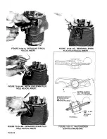
Страница 188: ...URE 72 20 148 EXPANDING SPARK PLUG HOLE HELICAL INSERT 72 20 10 FIGURE 72 20 14C REMOVING SPARK PLUG HOLE HELICAL INSERT II L _ A THESE SURFACES MUST BE SQUARE WITHIN 002 IN FU LL INDICATOR READING INTERNAL CHAMFER ONL Y AS RECEIVED INSTAll AT OUTER END SECTION A A FIGURE 72 20 17 VALVE ROCKER BUSHING DIMENSIONS ...

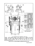
Страница 189: ...ensions shown are finish size after honing ZERO INDICATOR AT THIS POINT TO CHECK CHOKE 0 X Y Diameter Service limit is D Diameters Max 003 of an inch CAUTION Cylinder assemblies exceeding new parts dimension shown are acceptable when performing maintenance before engine overhaul However piston ring gaps given In the table of limits should be maintained When engine is being overhauled rCM recommend...

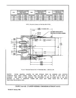
Страница 190: ...OKE I tt _C H 0 K E_ _ 4 7 5 STRAIGHT AREA 4 25 IT 5 433 5 429 0 DIA 6 50 4 lJ 5 75 tt 11 6 425 6 420 6 500 6 490 0 X Y Diameter Service limit is D Diameters Max 003 of an inch CAUTION Cylinder assemblies exceeding new parts dimension shown are acceptable when performing maintenance before engine overhaul However piston ring gaps given in the table of limits should be maintained When engine is bei...

Страница 191: ...OCEDURE BY HAND VALVE GUIDE REMOVAL 1 Use a No 4981 Remover Select proper size head Install on removing handle Attach to cold water supply 2 Heat cylinder to 550 600 F Heat soak one hour 3 Install pilot into guide Hold down firmly into guide bore with hand on water release button Use other hand to work sliding hammer Release the water and hammer out guide while water is running 80th guides can be ...

Страница 192: ...IFTERS See Figure 72 20 18 Stand valve lifter on its flat end Use a small screwdriver and carefully pry snap ring 1 from body groove holding down socket 2 with a pushrod until ring has been removed Invert lifter and catch socket as it drops out Insert a finger into plunger 3 and withdraw plunger 3 spring 7 and check valve assembly 3 4 5 6 If plunger is stuck in body 8 hold plunger down fully and s...

Страница 193: ...R WAS COMPlETEl Y REMOVEO BY BORING OR REAMING OF REPLACEMENT BUSHING 1 00 WEIGHTS OF RODS IN ANY ENGINE MUST BE SAME WITHIN OZ IN OPPOSITE BAYS FIGURE 72 20 20 CONNECTING ROD AND BUSHING DIMENSIONS 72 20 21 CRANKSHAFT ASSEMBLY Raised edges from small nicks on hard surfaces such as crankpins and journals can be removed with a hard Arkansas stone Do not use a coarse abrasive Do not attempt to remov...

Страница 194: ...l indicator reading CAUTION Before boring a new bushing plug its oil holes with beeswax to exclude chips from the adaptergroove Be sure to remove the wax completely after the operation The old seal may be driven out with a 1 8 inch diameter pin punch inserted through the four oblique oil holes in the bushing boss alternately If the seal is too tight for that method drill and tap two opposite machi...

Страница 195: ... them On TCM harness assemblies push the cable end through the outlet plate and install the inner ferrule grommet and outer ferrule eyelet onto cable center wire On Slick harness assemblies push the cable end through the outlet plate and install the tapered drive ferrule press drive ferrule into outlet plate install insulator sleeve spring on electrode screw and screw into cable end Observe the P1...

Страница 196: ...72 20 18 February 1989 INTENTIONALLY LEFT BLANK ...

Страница 197: ...ports and Inquiries 72 30 05 Fluorescent Particle Inspection 72 30 06 Dimensional Inspection 72 30 07 Dimensional Limits 72 30 08 Table of Limits 72 30 09 Original Dimension 72 30 10 New Parts and Service Limits 72 30 11 Critical New Parts Dimensions 72 30 12 Protective Coating 72 30 13 Application of Alodine 72 30 14 Repair of Alodine Surfaces 72 30 15 Enamel Coatings ...

Страница 198: ... steel surface may appear dull scuffed or corroded depending on length of time subjected to the action GALLING Excessive friction between two metals resulting in particles of the softer metal being torn away and welded to the harder metal INDENTATION Dents or depressions in a surface caused by severe blows OXIDAnONS Chemical combining of a metal with atmospheric oxygen Aluminum oxide forms a tough...

Страница 199: ...rts should be in three groups potentially serviceable parts reparable parts and parts to be discarded 72 30 03 MAGNETIC PARTICLE INSPECTION Prior to performing a Magnetic Particle Inspection verify the parts are clean and free of dirt carbon varnish gum and paint CAUTION Prior to Magnetic Particle Inspection ensure that the parts have been thoroughly cleaned and dried according to Engine Cleaning ...

Страница 200: ...g Rod Magnetic Particle Inspection instructions Circular and Longitudinal 1500 All areas Cracks Camshaft Circular and Longitudinal 1500 Lobes Journals Drilled hole edges Heat stress cracks Cracks Rocker arms On conductor bar and single 1000 Pad Socket under side arms and boss Cracks Between heads 800 Gears up to and including six inches in diameter Circular or on Center Conductor 1000 to 1500 Teet...

Страница 201: ...and Training Services PQT 806 Botany Road Greenville SC 29615 Phone 864 292 1115 www PQT net B Crankshaft Ultrasonic Inspection See Section 1 20 01 Special Tools for equipment requirements and availability 1 Perform an Ultrasonic Inspection on the crankshaft according to the latest version of Continental Motors Material Handling Specification MHS 200 WARNING Do not steel stamp the inspection resul...

Страница 202: ...service Mutilate the crankshaft to identify it as Unairworthy Replace the crankshaft with a new one V U VAR Steel Ultrasonic Inspected Figure 72 30 1 EXAMPLE 1 U Non VAR Steel Ultrasonic Inspected Figure 72 30 1 EXAMPLE 2 Table 15 31 Parts requiring Fluorescent Penetrant Inspection Inspect Pay particular attention to Accessory Drive Adapters Brackets Crankcase halves Cylinder heads Engine mounts I...

Страница 203: ...linder bore gage is preferred rather than tools not specifically designed for this purpose Clearances in the new part limits apply to mating parts 72 30 07 DIMENSIONAL LIMITS After comparative measurements of mating parts and determination of running clearance refer to the Table of Limits Section 72 30 08 and to the Limits Charts 72 30 08 to locate the reference number of each fit and the acceptab...

Страница 204: ...04 is provided for which dimensional limits cannot be specified to determine their suitability for continued use TeM also provides Service Limits information for re usable parts They are intended as a guide line for re use when performing maintenance of the engines prior to major overhaul Parts with dimensions or fits that exceed service limits should not be used Parts with values up to and includ...

Страница 205: ...dler gear and magneto drive gear right and left 4 Starter shaftgear and crankshaft gear Description DSee Section 72 30 10 New Parts and Service Umits CD Serviceable Umlt Backlash 0 0160 Backlash 0 0160 Backlash 0 0160 Backlash 0 0160 NewParta Min Max 0 0080 0 0120 0 0080 0 0120 0 0080 0 0120 0 0080 0 0120 February 1989 72 30 09 ...

Страница 206: ... rocker arm bearing Diameter O OO4OL 0 OO10L O OO25L 15 Rocker arm bearing in rocker arm Diameter O OO2OT O OO4OT 16 Rocker arm Side Clearance O 035OL O C020L 0 OO15L 17 Rocker arm to rotocoil Clearance 0 20 18 Rocker arm grind Width 0 34 19 Intake valve in guide Diameter O OO5OL 0 OO12L 0 0027L 20 Exhaust valve in guide niresist Diameter 0 OO70L O OO3OL 0 0047L 20 Exhaust valve in guide nitralloy...

Страница 207: ...meter 0 0000 0 OO18L 42 Connecting rod bearing on crankpin Diameter O OO6OL O OOO9L O OO34L 43 Connecting rod on crankpin End Clearance 0 Q160 0 0060 0 0100 44 Connecting bearing and bushing twist or convergence per inch of length 0 0010 0 0000 O OOOS CRANKCASE AND ATIACHED PARTS 45 HydrauliC lifter in crankcase Diameter O OO35L 0 0010L 0 002SL SPRING TEST DATA 46 Inner valve spring 631S21 compres...

Страница 208: ...ECTION I I I N I W Q Q I r I f l _1 m r m 0 U 11 1_ 1 1 7 A iJ JA iiijji iliiiliillP l mrni v jIIlIlIlIIllIlIlIlIlI lIlIlIlIlIlIIIl1II11I1UUIIUUIIIIIIIIIIIIIIII II r I i en 0 r I 23 46 47 u 11 t N j _ I 21 45 I 25 L VALVE SPRING _ _ _ HEIGHT _ 0 _ 22 trn 12 18 24 9 20 10 SECTION A A ...

Страница 209: ...amshaft Diameter CRANKCASE AND ATTACHED PARTS Through bolt in crankcase Diameter Idler gear support pin in crankcase front Diameter Idler gear support pin in crankcase rear Diameter Oil pump housing pilot in crankcase Diameter ACCESSORY DRIVE IDLER ARM Bushing in idler gear Diameter Idler gear support in bushing Diameter Idler gear End Clearance CD For modified crankshaft engines See Modified B Se...

Страница 210: ...r 0 0100L 29 Scavenge pump drive and driven gear in scavenge pump End Clearance 0 0050 30 Oil pump driven gear shaft in oil pump housing Diameter 31 Oil pump driven gear on shaft Diameter O OO4OL Oil pump driven gear in housing Diameter O OO8OL 32 Oil pump driven gear in housing Diameter O OO6OL 72 30 14 February 1989 New Parts Min Max O OO55L O OOBOL O OO55L O OO8OL 0 0005 0 0030 0 0010T O OO3OT ...

Страница 211: ...FIGURE 72 30 08 TABLE OF LIMITS CHART 3 72 30 15 ...

Страница 212: ...DRIVE ASSEMBLY 9 Tachometer drive shaft in oil pump cover Diameter 0 0045L 0 0015L O OO3OL 10 Oil seal in tachometer drive housing Diameter 0 0010T 0 0070T GEAR BACKLASH 11 Oil pump driver and driven gears Backlash 0 0270 0 0140 0 0128 Oil pump driver and driven gears Backlash 0 0160 0 0090 0 0130 12 Scavenge pump driver and driven gears Backlash 0 0270 0 0140 0 0218 13 Tachometer drive gear and t...

Страница 213: ...3 11 SECTION A A 4 5 6 IVf 7 8 SECTION C C SECTION 0 0 9 10 16 SECTION B B 7 1 SECTION C C SECTION E E FIGURE 72 30 08 TABLE OF LIMITS CHART 4 5 6 10 12 72 30 17 ...

Страница 214: ...0 0010L O OOSOL STARTER DRIVE 12 Starter shaftgear in bearing Diameter 0 0031L O OOO5L 0 002OL 13 Starter shaftgear front bearing journal Diameter 0 7480 0 7495 0 7500 Starter shaftgear in clutch drum bearing Diameter O OOOSL o o02OL 14 Starter clutch drum on starter shaftgeat Diameter O OO55l 0 002Ol O OO4OL 15 Clutch spring sleeve in starter adapter Diameter O OO3OT O oo50T 16 Starter shaftgear ...

Страница 215: ...ter worm wheel gear and worm gear Governor drive gear and governor driven geac 23 15 22 14 12 13 Diameter Diameter Diameter Diameter Diameter Diameter Side Clearance Backlash Backlash 9 29 26 31 28 32 SECTION 8 8 Serviceable Limit New Parts 0 5600 0 0040L O 0300L 0 0200 0 0120 Min O OOOH 0 5615 0 0007T 0 0005L O OO50L 0 0010L 0 0100L 0 0090 0 0040 11 6 dk 8 7 4 1 3 5 SECTION 0 0 lAn 9 10 SECTION E...

Страница 216: ... Rod Bushing Bore Diameter 1 1267 1 1269 Bushing Center to Crankpin Center 6 6230 6 6270 Crankshaft Assembly Damper Pin Bushing 1 0 16 0 6240 0 6260 Camshaft Journal Diameter 4 1 2480 1 2490 Hydraulic Valve Tappets Outside Diameter 0 990 0 995 Crankcase Camshaft Bearings Diameter 1 2500 1 2510 Tappet Guides Diameter 1 0005 1 0015 Governor Driven Gear Bearing Diameter 0 8750 0 8760 Starter Shaft Ne...

Страница 217: ...a Sandcast Crankcase CDMeasure piston diameters at right angles to pin bore NEW DIMENSION INCHES 0 7900 0 7910 2 3740 2 3760 1 9380 1 9400 2 3380 2 3430 0 5600 0 5605 0 5620 0 5630 0 5015 0 5025 0 5620 0 5630 2 6235 2 6250 0 8120 0 8130 0 7925 0 7975 0 7900 0 7950 0 8095 0 8105 72 30 12 PROTECTIVE COATING The manufacturer protects all aluminum alloy castings sheet metal and tubing from corrosion b...

Страница 218: ...ion flows over bare area Allow solution to remain on the part from one to five minutes or until color of the new film is approximately same as original D Flush part with clear water and dry with warm air current Do not air blast or rub with cloth to dry new film area If color is too light repeat step c until desired color is obtained NOTE If Accelagold does not adhere to metal a more severe cleani...

Страница 219: ...0 07 72 40 08 72 40 09 72 40 10 72 40 11 72 40 12 72 40 13 72 40 14 72 40 15 Crankcase Crankshaft Crankshaft Counterweight Pins and Bushings Camshaft Connecting Rods Gears Pistons Cylinders Hydraulic Valve Ufters Intake Tubes Lubrication System Fuel Injection System Ignition System Exhaust System Inspection Chart 72 40 01 ...

Страница 220: ...72 40 02 INTENTIONALLY LEFT BLANK ...

Страница 221: ...opeller Refer to the Table of Umits 72 30 09 for limits of run out at the center joumal NOTE In case of prop strike sudden stoppage refer to the latest Prop Strike Accident Service Bulletin 72 40 03 CRANKSHAFT COUNTERWEIGHT PINS AND BUSHINGS A Excessive localized galling of the crankshaft damper pin bushings can affect propeller blade tip stresses It is recommended that at each normal major overha...

Страница 222: ...ch as specified in Section 72 30 08 Table of Umits 72 40 06 GEARS Inspect gear teeth for signs of overheating and excessive wear Normal wear produces a fine polish on the tooth thrust faces Alteration of the tooth profiles score marks and pitting are sufficient cause for rejection 72 40 07 PISTONS AND RINGS Inspect the skirt for long deep scores which indicate overheating and would be sufficient c...

Страница 223: ...iston lands Make certain part number is toward piston head Now measure ring side clearance as follows 1 Hold a straight edge against the side of the piston ring grooves adjacent to the piston pin relief as shown in Figure 72 40 07A FIGURE 72 40 07A INSPECTING RING SIDE CLEARANCE 6 44 FIGURE 72 40 07B MEASURING RING GAP INCYUNDER February 1989 72 40 05 ...

Страница 224: ... length if the stem tips were ground If there was any evidence of overheating of cylinder or piston check for possible turning of the head in relation to the barrel flange Security between cylinder head and barrel is dependent on metal to metal contact of cylinder barrel top threads within the head shoulder Dark stains at this area on both new and rebarreled cylinders is generally due to emission ...

Страница 225: ...t of filter is pink moisture is present and filter should be replaced At the same time inspect hoses for weather checking and leaking Magnetos should be disassembled and inspected at each 500 hour interval according to Magneto Service Manual SPARK PLUGS See Figure 72 40 13 Teledyne Continental Motors aircraft engines utilize the two spark plug per cylinder configuration to provide a more efficient...

Страница 226: ... Out Severe Excessive eroded center and ground electrodes and extensive necking of fine wire ground electrodes indicate abnormal engine power operation Check fuel metering and magneto timing Discard the plugs and before installing new spark plugs a careful check should be made to determine if proper heat range plugs are being used FIGURE 72 40 13A SPARK PLUGS 72 40 08 Reduce wear of spark plug ele...

Страница 227: ...Elbows Inspect these components for burned areas cracks and looseness DUring this inspection give special attention to the condition of welded areas and seams for cracks E Heater Muff Special attention should be given in the pressurized exhaust system inspection If air bubbles arise with the soapy water replace heater muff F Slip joints Figure 72 40 14A Visually inspect slip jOints for bulging and...

Страница 228: ...0 14A SlIPJOINT ASSEMBLY T BOLT FASTENER INNER SEGMENTS MUST NOT OUTER BAND INNER SEGMENT RADII INNER SEGMENT OUTER BAND CONTACT 100 LESSTHAN 062 INCH CLEARANCE f 1 NNERSEGMENT OUTER BAND J ULJlJ NORMALLY FLAT FIGURE 72 40 14B MULTI SEGMENT V BAND CLAMP CONTACT AFTER TORQUING ...

Страница 229: ...ylinders as a quality check Scoring diameter flare at ends Roughness caused by honing Cracks and broken areas Special Considerations Clean inspect if seepage continues replace cylinder Defects not permissible after removal of glaze Refer to Table of Umits tor standard size bore or for oversize bore Dimensional honing should remove ring step of more 0 002 inch diameter Taper limit Table of Umits mu...

Страница 230: ...has not cut through Stellite face of exhaust valve or entered rounded edge on intake valve head Valve Length Use height gage to detect Stretched valves may fail stretch and check for ra Shortened valve may exceed duction due to tip grinding ability of hydrauliC lifters to take up lash Valve Rockers Contact Foot Scoring diameter Oil Passages Obstruction Hub Side clearance between Refer to Table of ...

Страница 231: ... hand only Oil Control Plug Presence Obstruction of oil hole tight fit Gear Teeth Screw Burring scoring wear enough Threads to alter profile Damaged or dirty threads CAMSHAFT ASSY Camshaft Journals Diameter and fit in crankcase Excessive bearing wear may bearings Scoring pitting and be compensated by enlarging corrosion bearing and installing over size shaft Refer to Crank case Lobes Pitting along...

Страница 232: ...rty threads Studs Threads Distortion Height Check for backing outs Refer to Stud Height Table Squareness Use toolmaker s square to Refer to Stud Height Table check studs suspected of bending Idler Gear Bore Inside diameter scoring Refer to Table of Limits Support and Bushings Needle Bearing Rollers Roughness or excessive play Retainer Mounting Surface Warpage cracks Observe Oil Seal that old seal ...

Страница 233: ... Damaged threads cracks around holes Mounting Surfaces Scratches warpage cracks All Areas Cracks Plugs Threads Look for distortion Wrench Flats Look for damaged corners Oil Suction Threads Tube Damaged threads dented Tube Filter tube cracks in tube distorted or plugged filter Engine Mounting Machined Scratches cracks Brackets Surfaces OIL PUMP ASSY Housing All Areas Cracks scratches on machined su...

Страница 234: ...ly in housing Oil Pressure Plunger Seat Spread Prussian blue oil Relief Valve base pigment on face of Housing plunger and turn on seat all around plunger face must be lapped to seat Plunger held centered and aligned Oil Pump Cover Shaft Holes Measure diameters Refer to Table of Umits Tachometer Threads Flange Thread distortion warped See that old oil seal was Drive Housing Seal Bore mounting surfa...

Страница 235: ...o alter tooth profile Ball Bearing Balls Cage Surface roughness out of round excessive depth and looseness Adapter Cover All Areas Cracks scratches on machined surfaces damaged mounting holes Shaft Bearing Look for scoring Bore Measure diameter Oil Seal See that oil seal was removed without damage to casting INDUCTION SYSTEM Intake Manifold Flanges Check tor warping by placing flanges on surface p...

Страница 236: ...f Umits compare with bore diameter Gear Plug Make sure that new plug was installed after magnetic particle inspection of gear and visual inspection for cleanliness of center bore Drive Coupling Fit Check for looseness Fuel Pump and Outside Area Inspection is limited strictly Vapor Separator to visual for evidence of damage or deterioration Fuel Injection Control Assy Fuel Manifold Valve Assy Shrou...

Страница 237: ...on or stripping Wrench Flats Look for damaged corners MAGNETO AND ACCESSORY DRIVE ASSEMBLY Adapter Gear Bushing Measure bore diameters Refer to Table of Limits Oil Seal Observe that old seal has been removed without damage to casting bore Studs Look for stripped and deformed threads Gear Teeth Scoring burring or wear enough to alter tooth prOfile Shaft Measure diameters and Refer to Table of Limit...

Страница 238: ...72 40 20 INTENTIONALLY LEFT BLANK ...

Страница 239: ...50 02 Oil Pump Assembly 72 50 03 Starter and Drive Assembly 72 50 04 Cylinder Assembly 72 50 05 Piston and Ring Assemblies 72 50 06 Pushrod Housing 72 50 07 Crankshaft and Connecting Rods 72 50 08 Camshaft 72 50 09 Crankcase 72 50 10 Fuel Injection Control and AIr Throttle Body Assembly 72 50 01 ...

Страница 240: ...72 50 02 INTENTIONALLY LEFT BLANK ...

Страница 241: ...it in that condition If part is accidentally tightened too much loosen it and retighten it to a value within the specified limits If a nut slot cannot be aligned with a cotter pin hole within the specified limits substitute another serviceable nut If the cotter pin hole in stud lies beyond the nut slots when the nut has been tightened properly the stud has been improperly installed or has backed o...

Страница 242: ... 4 20 45 55 3 8 4 6 Intake Flange Screw 1 4 20 85 110 7 1 9 2 Oil Cooler to Adapter Bolt 1 4 20 100 110 8 3 9 2 Oil Pump Cover to Crankcase Bolt 1 4 20 75 85 6 3 7 1 Collar Assy Gov Oil Transfer Nut 1 4 28 75 85 6 3 7 1 Spirotallic Exhaust Gasket Assy Attaching Manifold Flange Nuts 1 4 28 100 110 8 3 9 2 Alternator Mounting Bolt 5 16 18 150 180 12 5 15 0 Rocker Shaft Hold Down Bolts 5 16 24 85 110...

Страница 243: ...ngine lubricating oil except where special lubricants are mentioned in the text In some instances where gears and other running parts are accessible after assembly in a housing additional oil should be applied to assure full coverage Before installing tapered pipe plugs or straight thread plugs To prevent seizure and leakage of oil coat the male threads with anti seize compound Coat both sides of ...

Страница 244: ...f valve housing 12 about halfway Secure with copper washer 14 and nut 15 Install new gasket 11 washer 9 spring 8 and plunger 7 onto adjusting screw and assemble into housing 2 B Install driven gear 5 6 on shaft in housing 2 Install driver gear 16 in pump housing to mesh with driven gear Apply Permatex and silk thread to parting surface See Chapter 70 Standard Practices C Secure with attaching part...

Страница 245: ... 400 450 in lbs NOTE The sheave is not keyed to the shaft therefore there are no timing marks for the engine on the sheave The engine timing marks are located on the outside diameter of the propeller flange When the TC mark is lined up with the lower crankcase splitline No 1 cylinder is at TDC 72 S0 04 CYUNDER ASSEMBLY ALL EXCEPT TS10 520 AE See Figure 72 10 14A Each cylinder should have its posit...

Страница 246: ...he crankcase secure the pushrod with clip 35 and washers and nuts 36 37 SPRING VALVE INNER SPRING VALVE OUTER RETAINER VALVE GUIDE INSERT INSTALLED ilill SPRING HEIGHT SEE DIMENSIONS IN TABLE OF LIMITS NOTE INNER AND OUTER SPRINGS MUST BE INSTALLED AS SHOWN WITH CLOSED COILS TOWARD CYLINDER HEAD Figure 72 50 07 VALVE SPRING INSTALLATION 72 50 05 PISTON AND RING ASSEMBLIES See Figures 72 1o 14A B A...

Страница 247: ...31 and tap gear onto crankshaft Attach gear to shaft with six screw 25 to specified torque and secure head with lockwire See Chapter 70 Standard Practices F Remove spring 27 and reinforcing ring 28 from oil seal 29 Unhook the spring ends using and unwinding motion Wrap spring around shaft in seal area turn spring ends in an unwinding direction then join and allow one end to wind into the other end...

Страница 248: ...nection fitting NOTE General instructions for reassembly of fuel injection components will apply to all engine models NOTE The fuel injection equipment is calibrated with plugs and fittings intact Removal of any of these parts could allow small metal shavings to become lodged in the equipment Prior to reassembly any replacement fittings should be screwed into proper size holes in a block of soft w...

Страница 249: ...fittings 31 32 33 36 and tubes 34 35 Install new wave washers 12 on link assemblies 13 thru 17 and install link assemblies on turbo control throttle fuel control secure with washers 11 and cotter pins 10 Final adjustment will be established at final assembly 1800 I _ _ _ _ _ _ _ _ 1 I 00 FIGURE 72 s0 10A FUEL MANIFOLD VALVE FITI1NG LOCATIONS FOR TSIO S20 CE A B C TSIO S20 CE 90 ELBOW 270 90 ELBOW ...

Страница 250: ... D C D FIGURE 72 50 108 FUEL MAINFOLD VALVE FITIING LOCATIONS FOR TSIO 520 C G H M P R T AE AF A B C 0 E 90 ELBOW 0 90 ELBOW 180 NIPPLE UNION 45 ELBOW 90 ELBOW 0 90 ELBOW 180 NIPPLE UNION 45 ELBOW 45 ELBOW 135 90 ELBOW 270 90 ELBOW 270 90 ELBOW 225 90 ELBOW 0 ...

Страница 251: ...IXTURE FUEL FUEL OUTLET RETURN INLET OUTLET A B C D E TSIO 520 C G H Plug 90 Elbow 300 Plug 45 Elbow 165 Connector TSIO 520 M P R AF Plug 90 Elbow 300 Plug 90 Elbow 165 Connector TS O 520 T 90 Elbow 270 45 Elbow 290 Plug 90 Elbow 315 Connector TSIO 520 CE Plug Tee 225 Plug Tee 135 Connector 72 50 13 ...

Страница 252: ...ATIONS FOR TSI0 520 T MODEL INLET OUTLET MIXTURE VAPOR DECK SEAL RETURN RETURN PRESS REF DRAIN A B C D E F TSIO 520 T 45 Elbow 90 Elbow 90 Elbow 90 Elbow 90 Elbow Adapter 270 90 60 15 0 Connector Connector 45 Elbow 105 72 50 14 February 1989 ...

Страница 253: ...FIGURE 72 S0 10E FUEL PUMP FITTING LOCATIONS FOR TSIO S20 AE Inlet Outlet Vapor SIC Press Seal SIC Press Fitting Fitting Return Fitting Drain Fitting Fitting Fitting A B C 0 E F 130 200 0 0 0 February 1989 72 S0 1S ...

Страница 254: ...F E c FIGURE 72 50 10F FUEL PUMP FllTlNG LOCATIONS FOR TSI0 520 C G H M P R AF CE 72 50 16 February 1989 ...

Страница 255: ...nnector Connector 45 Elbow 45 Elbow 100 0 TSI0 520 M P R 45 Elbow 900 Elbow 90 Elbow 90 Elbow Elbow 270 Adapter 235 90 60 15 Connector Adapter Connector 45 Elbow 45 Elbow 100 0 frSl0 520 AF 45 Elbow 90 Elbow 90 Elbow 90 Elbow Elbow 270 Adapter 235 90 60 350 Connector Adapter 45 Elbow 45 Elbow 100 90 ITSI0 520 CE 45 Elbow 90 Elbow 90 Elbow goO Elbow Nipple 90 Adapter 235 90 60 0 Connector Adapter 4...

Страница 256: ...THROTTLE METERING ASSEMBLY FUEL OUTLET FIGURE 72 S0 10G AIR THROTTLE METERING ASSEMBLY FITTING LOCATIONS FOR TSIO S20 AE 72 S0 18 February 1989 ...

Страница 257: ...72 60 15 72 60 16 72 60 17 72 60 18 72 60 19 General Crankcase Cylinders and Pistons Oil Pump Fuel Pump Starter Drive Adapter Alternator Assembly Magneto and Accessory Drive Adapters Oil Cooler Valve Mechanism Oil Sump Induction System Fuel Injection System Magneto Drive Gears Placing Crankshaft in Timing Position Magnetos Ignition Harness Fuel Unes Hoses Exhaust System 72 60 01 ...

Страница 258: ...72 60 02 INTENTIONALLY LEFT BLANK ...

Страница 259: ...crankcase bearings with oil seal positioned so it enters the seal cavity in the crankcase The connecting rod position numbers if properly installed will be toward the upper case flange Carefully lay odd numbered rods on the upper case flange C Insert governor driven gear See Figure 72 10 16 into its bearing D Lay camshaft assembly in its bearings in left crankcase Mesh spur gear teeth with those o...

Страница 260: ...FIGURE 72 6o 02A LEFT CRANKCASE AND SHAFTS ASSEMBLED ON STAND 1 Crankshaft Gear Timing Marks 2 Camshaft Gear Timing Mark FIGURE 72 60 02B ALIGNMENT OF TIMING MARKS 72 60 04 ...

Страница 261: ...17 and thru bolts 10 13 18 to 300 400 inch Ibs in sequence shown 5 Install cylinder No 6 Tighten stud nuts 20 21 23 24 25 26 and thru bolts 19 22 27 28 29 to 300 400 inch Ibs in sequence shown 6 Install cylinder No 1 Tighten stud nuts 31 32 34 35 36 37 and thru bolts 30 33 38 to 300 400 inch Ibs in sequence shown 7 Torque thru bolts and stud nuts 1 thru 38 to the correct torque values in sequence ...

Страница 262: ...er 28 lifting eye 27 and secure with attaching parts 26 25 24 23 22 21 Install attaching parts 60 through 63 M Install one bolt 47 washers 48 49 at left rear one O ring 50 two bolts 47 washers 48 49 at right rear and one bolt and washer 47 48 at right front Do not tighten any parts in this group at this time N Seat gasket 42 and idler gear support pin 41 The eccentric shoulder must be away from cr...

Страница 263: ...should be positioned 180 apart with the first or top ring gap toward top of piston D Install pistons and cylinders in desired order It is suggested that Nos 4 and 5 be installed first to minimize turning of the crankshaft and to prevent excessive unbalance Turn the crankshaft for Nos 2 and 3 and install the assemblies Then turn the shaft for Nos 1 and 6 and install the last two assemblies E Place ...

Страница 264: ... cylinder pad Install but do not tighten attaching parts 18 19 or 42 43 Top four nuts should be installed first H After installing all pistons and cylinders tighten and torque nuts according to sequence shown in Figure 72 60 2C Torquing Sequence I Install spark plugs and gaskets in upper cylinder holes 72 60 04 OIL PUMP See Figure 72 10 13 72 60 08 TS10 52o C G H M P R AF A Remove two sets of atta...

Страница 265: ...gasket and pump assembly on crankcase studs Install attaching parts and torque to values specified in Table of Umits Section 72 30 08 E Tighten oil filter cap and left hand threaded tachometer drive housing 72 60 0S FUEL PUMP See Figure 72 10 06A B C A Lubricate fuel pump drive gear with Molyshield grease B Install gear in pump Install new gasket and mount fuel pump and vapor separator on crankcas...

Страница 266: ...n pushrod housing insert crankcase end of housing into crankcase guide compressing spring until other end with washers 16 and seal 17 already installed can be aligned with cylinder head opening Move assembly outward until housing seal has entered cylinder hole Release spring slowly until it is free and remove spring compressor see figure 72 60 10 On Straight valve cylinders with o rings 33 and was...

Страница 267: ...ING PUSHROD HOUSING 1 Valve Rocker Cover 2 Washer Lockwasher Screw 3 Oil Suction Tube 4 Hydraulic Valve Lifter 5 Oil Gauge Rod Support 6 Bolt FIGURE 72 60 11 BOTTOM VIEW WITH VALVE MECHANISM AND OIL SUMP SUCTION TUBE 72 60 11 ...

Страница 268: ... 6 and gasket 7 position it on the crankcase D Lay sump on crankcase and install attaching parts 3 4 5 Make sure plug and gasket 1 2 are installed and tight 72 60 12 INDUCTION SYSTEM See Figure 72 10 0SA thru D A Push a new applicable hose on either end of intake manifold elbows Slide one hose clamp to a position midway on overlapping portion Tum each clamp so that a screwdriver can be aligned wit...

Страница 269: ...nd washers 5 Compression seal 4 on sleeve can be replaced if necessary Install air manifold tubes 1 2 on each bank Install hose between 2 4 6 side and 1 3 5 side air manifold tubes B Loosely assemble intake elbows and install on the respective cylinders using new gaskets 29 Tighten finger tight Install balance tube 16 and secure bracket 17 to sump rail Position hoses and secure clamps lighten inta...

Страница 270: ... into crankcase with plug 39 B Coat both sides of gaskets 33 37 with a film of TCM Gasket Sealant PIN 642188 Insta gasket 37 on mounting studs and slide fuel pump adapter 36 with seal 35 over studs Insta gasket 33 insulator 34 and gasket 33 then install fuel pump 32 and secure with four sets of attaching parts 29 30 31 Install shroud 28 and secure with attaching parts 25 26 C Install one hose asse...

Страница 271: ...See Figures 72 10 07 72 60 14 A With engine in upright position insert one pressed steel retainer 22 into each gear hub slot B Cover each of four new rubber coupling bushings with a film of Molyshield grease and insert two bushings 21 into each retainer rounded long edges first C Turn the crankshaft to the No 1 cylinder advance firing angle as described in Section 72 60 12 Install sleeve 19 into m...

Страница 272: ...tation until piston lightly touches TDC locator 4 Rotate disc of timing indicator until top center mark is under the pOinter 5 Slowly turn crankshaft in opposite direction until piston lightly touches TDC locator Observe reading on disc under the pointer and move the disc to exactly one half of the number of degrees observed toward the top center mark You have now located top dead center 6 Remove ...

Страница 273: ...ind magneto drive gears and attach with four sets of plain washers lockwashers and nuts 72 60 17 IGNITION HARNESS See Figures 72 10 05 72 20 27 72 60 17 A The high tension cable outlet plates can be attached to either magneto in only one position The very shortest ignition cable is for No 1 upper spark plug and identifies proper assembly for the right magneto Notice the 1 on the outlet plates next...

Страница 274: ...ufacturers regarding tips for increased service life I On engines equipped with pressurized magnetos Ref 72 10 05 reconnect pressurization tubes 55 to throttle or air manifold as applicable USing new hoses 54 filter 56 and clamps 53 reconnect tube 55 filter 56 and tee 57 to both magnetos 27 UPPER SPARK PLUGS RIGHT MAG SWITCH RIGHT MAG LEFT MAG SWITCH LEFT MAG 2 J ry V ________________ ____________...

Страница 275: ...s with special nuts 31 Do not tighten at this time B Assemble exhaust tube 35 and cross pipe and turbine flange assembly 36 to exhaust tee and elbow assemblies C Position turbocharger 30 on flange assembly 36 and secure both to bracket 38 with attaching parts 27 28 29 D Use new gaskets 8 and secure bypass valve assembly to cross pipe 6 Attach tailpipe assembly to bypass valve with four bolts nuts ...

Страница 276: ...72 60 20 INTENTIONALLY LEFT BLANK ...

Страница 277: ... 03 Cooling Air Scoop 72 70 04 Induction Air Intake 72 70 05 Exhaust Stacks 72 70 06 Controls 72 70 07 Electrical Wiring 72 70 08 Instruments 72 70 09 Breather 72 70 10 Fuel System 72 70 11 Governor Pad Cover 72 70 12 Engine Test 72 70 13 Starting Procedure 72 70 14 Overhaul Test Run 72 70 15 Test Flight 72 70 01 ...

Страница 278: ...72 70 02 INTENTIONALLY LEFT BLANK ...

Страница 279: ...dard diameters so that the blade length is reduced by the cut and try method The club will absorb the BHP at the RPM speCified in Section 72 70 14 Use the test club in combination with the cell test stand and operating limits for which it was calibrated 72 70 03 COOLING AIR SCOOP The scoop must be designed to fit over the tops of all cylinders with padded seals for rear cylinders and valve rocker ...

Страница 280: ...alternator circuit G Fuel flow gage or fuel pressure gage H A turbine inlet temperature gage I Manifold pressure gage 72 70 09 BREATHER A substantial hose of 3 4 inch 10 should be securely clamped over crankcase breather elbow and support so as to lead to a point above and to the rear of engine 72 70 10 FUEL SYSTEM The test stand fuel system is to incorporate an auxiliary pump capable of deliverin...

Страница 281: ... section after a major overhaul Standard Acceptance Test NOTE If tests must be conducted in extremely cold weather it may be necessary to shield the crankcase from the cooling air stream since it takes some heat from the oil CAUTION The engine should be run at idle RPM approximately 1 minute before shutdown to allow the turbocharger to spool down and thus prevent starvation of needed lubricating o...

Страница 282: ...il Temperature M A P C H T and Alternator Magneto Drop and Spread To Be Taken Engine Must Be Throttled To Specified RPM and Temperature Allowed To Settle Out Before Taking Magneto Drop And Spread Mag Check 2100 RPM LJTSI0 520 AE 1700 RPM Cooling Period 3000 Max C H T Before Shut Down Recheck Idle Adjustments Runs 8 And 9 Must Be Made With Stops For Leak Checks At The End Of Each Run The Engine Wil...

Страница 283: ...re Reduce RPM For Adjustments Check Fuel Injection Oil Pressure Oil Temperature M A P C H T and Alternator Magneto Drop and Spread To Be Taken Engine Must Be Throttled To Specified RPM and Temperature Allowed To Settle Out Before Taking Magneto Drop And Spread Mag Check 2100 RPM LJTSIO 520 AE 1700 RPM Refill sump with clean oil Readings must be recorded after completion of each 10 minute interval ...

Страница 284: ...AE TSIO 52D CE METERED FUEL PRESSURE AT IDLE PSI ALL MODELS EXCEPT CE TSIO 52D CE ENGINE INTAKE AIR TEMPERATURE ALL MODELS ENGINE INTAKE AIR PRESSURE MAX H20 TIC INLET ALL MODELS MANIFOLD PRESSURE AT FULL THROTTLE IN HG TSIO 52D C H AE TSIO 52D G TSIO 520 M P R TS10 520 T TSIO 520 AF TSIO 520 CE MANIFOLD PRESSURE AT IDLE IN HG ALL MODELS OIL GRADE 72 70 08 NORMAL SERVICE ABOVE 30 F BELOW 50 F ALL ...

Страница 285: ...ERATURE 1750 F 185 F OIL PRESSURE AT IDLE PSI MIN OIL TEMPERATURE 130oF 140oF IGNITION TIMING TSIO 52o C H AE CE LEFT MAGNETO BTe RIGHT MAGNETO BTe IGNITION TIMING TSI0 520 G M R T AF LEFT MAGNETO BTe RIGHT MAGNETO BTe IGNITION TIMING TS10 52o P LEFT MAGNETO BTe RIGHT MAGNETO BTe CYLINDER HEAD TEMPERATURE MAX WITH BAYONET THERMOCOUPLE CRANKCASE PERSSURE MAX IN H20 40 60 30 72 70 09 ...

Страница 286: ...72 70 10 INTENTIONALLY LEFT BLANK ...

Страница 287: ...SECTION 72 80 ENGINE PRESERVATION 72 80 00 ENGINE PRESERVATION 72 80 01 General 72 80 02 Flyable Storage 72 80 03 Temporary Storage 72 80 04 Indefinite Storage 72 80 01 ...

Страница 288: ...72 80 02 INTENTIONALLY LEFT BLANK ...

Страница 289: ...ented will minimize the detriments of rust and corrosion It is the owners responsibility to choose a program that is viable to the particular aircraft s mission Aircraft engine storage recommendations are broken down into the following categories A Flyable Storage Program I or II B Temporary Storage up to 90 days C Indefinite Storage 72 80 02 FLYABLE STORAGE Program I or II Program I Program II En...

Страница 290: ...used The spray head should have ports around the circumference to allow complete coverage of the cylinder walls NOTE Shown below are some approved preservative oils recommended for use in Teledyne Continental engines for temporary and indefinite storage MIL L 46002 Grade 1 Oils NOX RUST VCI 105 PETROTECT VA Daubert Chemical Company 4700 S Central Avenue Chicago Illinois Pennsylvania Refining Compa...

Страница 291: ...oles making sure that each plug is blue in color when installed Protect and support the spark plug leads with AN 4060 protectors 3 If the engine is equipped with a pressure type carburetor preserve this component by the follOwing method Drain the carburetor by removing the drain and vapor vent plugs from the regulator and fuel control unit With the mixture control in Rich poSition inject lubricati...

Страница 292: ...install the carburetor plugs and attach the fuel line 4 With bottom plugs removed rotate propeller to clear excess preservative oil from cylinders 5 Re install the spark plugs and rotate the propeller by hand through the compression strokes of all the cylinders to check for possible liquid lock Start the engine in the nonnal manner 6 Give the aircraft a thorough cleaning visual inspection and test...

Страница 293: ...mendation for our customers Since local conditions are different and Teledyne Continental Motors has no control over the application more stringent procedures may be required Rust and corrosion prevention are the owner s responsi bility 72 80 07 ...

Страница 294: ...72 80 08 INTENTIONALLY LEFT BLANK ...

Страница 295: ...10 00 SET UP PROCEDURE 73 10 01 Naturally Aspirated Engines 73 10 02 Turbocharged Engines 73 10 03 Fuel Pressure Regulators 73 10 04 Special Set Up Procedures 73 10 05 Fuel System Pressure and Flow Valve Charts 73 10 06 Fuel System Troubleshooting Chart 73 00 01 ...

Страница 296: ...73 00 02 INTENTIONALLY LEFT BLANK ...

Страница 297: ... no need for an intricate mechanism for timing injection to the engine The fuel pump is a two stage vane type pump of advanced design which has improved vapor suppression characteristics and performs well at high altitude and low inlet conditions It is driven directly by the engine and its flow rate depends on engine RPM An aneroid unit is incorporated as an integral part of the pump and functions...

Страница 298: ...73 00 04 INTENTIONALLY LEFT BLANK ...

Страница 299: ... idle RPM the variable orifice adjusting screw on turbocharged engines is located on the aneroid housing and is turned CW to decrease pressure and CCW to increase pressure CAUTION Jam nut must be loosened before screw can be adjusted Use care in both loosening and tightening this nut D Maintaining idle pump pressure and idle RPM correct idle mixture exists if upon leaning with the mixture control ...

Страница 300: ...just ments must be performed with the aircraft auxiliary pump on low position Refer to aircraft maintenance manual for details 73 10 02 FUEL PRESSURE REGULATORS Full throttle metered fuel flow adjustments must be accomplished as follows A Plug center retum port of fuel pressure limiter and plug end of detached line IMPORTANT DO NOT PLUG SIDE PORT INLET OF PRESSURE LIMITER B With pressure limiter r...

Страница 301: ...Hr 5 5 7 0 29 32 5 5 6 5 31 34 5 5 7 0 29 32 5 5 6 5 33 37 5 5 6 5 35 39 5 5 6 5 33 37 5 5 6 5 33 37 7 5 8 0 35 38 5 5 6 5 35 39 5 5 6 5 31 35 3 5 4 0 17 0 18 0 3 5 4 0 16 0 17 5 3 5 4 0 17 0 18 0 3 5 4 0 17 0 19 8 3 5 4 0 18 6 19 5 3 5 4 0 17 0 19 8 3 5 4 0 16 8 18 0 3 5 4 0 15 5 16 7 3 5 4 0 18 6 19 5 16 0 17 5 160 170 164 174 160 170 170 186 180 186 170 186 185 195 160 165 180 186 215 225 Fuel ...

Страница 302: ...tle clear engine of With Fuel Flow Gage excess fuel try another start Indication No fuel to engine Loosen one line at nozzle If no fuel shows with fuel flow on gage replace fuel manifold valve Rough Idle Nozzle restricted Remove nozzles and clean Improper idle mixture Adjust fuel air control unit in accordance with adjustment procedures Poor Acceleration Idle mixture incorrect Adjust fuel air cont...

Страница 303: ...ions jet in vapor separator cover Clean only with solvent no wires Air in fuel flow gage line Leak Repair leak and purge line at gage connection Poor Idle Cut Off Engine getting fuel Check mixture control is in full idle cut off Check auxiliary pump is OFF If neither replace manifold valve Unmetered Fuel Internal orifices plugged Clean internal orifices in injector Pressure pump Unmetered Fuel Rel...

Страница 304: ...73 10 06 INTENTIONALLY LEFT BLANK ...

Страница 305: ...0 01 Magneto Installation 74 00 02 Harness Assembly Installation 74 20 00 IGNITION TROUBLESHOOTING SUCK IGNITION SYSTEM 74 30 00 GENERAL 74 30 01 Magneto Installation 74 30 02 Harness Assembly Installation 74 50 00 IGNITION TROUBLESHOOTING February 1989 74 00 01 ...

Страница 306: ...74 00 02 February 1989 INTENTIONALLY LEFT BLANK ...

Страница 307: ...utomatically retard the spark during engine cranking The following detailed explanation gives the meaning of the various letters and numbers appearing in the type designations A S indicates single type ignition unit B 4 6 or 8 indicates number of cylinders fired C R or L indicates direction of rotation of rotating magnet viewed from drive end R for righthand L for lefthand D N indicates manufactur...

Страница 308: ...r proper torque Disconnect timing light from magneto Make connections between magneto and ignition switch using 18 gage wire following airframe manufacture s wiring instructions WARNING The magneto is in a SWITCH ON condition when the switch wire is disconnected Therefore the usual precaution must be observed 74 00 02 HARNESS ASSEMBLY INSTAllATION Before installing harness on magneto check mating ...

Страница 309: ...d torque as specified in Table II Tighten elbow assembly nuts to outer ferrule F1urocarbon Spray MS 8 122 Miller Stephenson Chemical Co Inc 16 Sugar Hollow Road Danbury Connecticut 06810 Go Jo No Lok Gojer Inc Akron Ohio 44309 or Molykote Type G The Alpha Molykote Corp Stamford Connecticut 06904 NOTE Hold ferrules while tightening or loosening spark plug coupling nuts to protect against twisting c...

Страница 310: ... improperly gapped Weak condenser Loose or improperly gapped spark plugs High tension leak in ignition harness Weak or burned out condenser as evidenced by burned or pitted breaker points Fouled or dead spark plugs Improperly gapped spark plugs Magnetos out of time Damaged magneto breaker points or condenser CORRECTION Tum switch On Check for grounded wires Remove and clean Adjust to proper gap Ti...

Страница 311: ... for the magneto The following detailed explanation gives the meaning of the various numbers appearing in the serial number E G 2 o 3 1 3 2 The year of Manufacture _____ J T 2 1982 The month of Manufacture 03 March 74 30 01 MAGNETO INSTALLATION AND TIMING TO ENGINE The number of a particular model manufactured in the month specified Before magnetos are installed on the engine the rotation and inte...

Страница 312: ... will indicate both magneto contacts are opening simultaneously at engine full advance firing position See Section 72 00 00 for correct firing position If contacts do not open within limits adjust magneto to engine timing as necessary Secure magnetos and remove timing lights CAUTION When installing the magneto on the engine using the available nuts and clamps please take the following precautions ...

Страница 313: ...2 Miller Stephenson Chemical Co Inc 16 Sugar Hollow Road Danbury Connecticut 06810 Go Jo No Lok Gojer Inc Akron Ohio 44309 or Molykote Type G The Alpha Molykote Corp Stamford Connecticut 06904 NOTE Hold ferrules while tightening or loosening spark plug coupling nuts to protect against twisting conduit or cable D Clamp harness leads as required Spark Plug Torque Coupling Thread in Ib 5 8 24 90 95 3...

Страница 314: ...improperly gapped Weak condenser Loose or improperly gapped spark plugs High tension leak in ignition harness Weak or burned out condenser as evidenced by burned or pitted breaker points Fouled or dead spark plugs Improperly gapped spark plugs Magnetos out of time Damaged magneto breaker points or condenser CORRECTION Turn switch On Check for grounded wires Remove and clean Adjust to proper gap Ti...

Страница 315: ...CHAPTER 75 AIR 75 00 00 GENERAL 75 00 01 ...

Страница 316: ...75 00 02 INTENTIONALLY LEFT BLANK ...

Страница 317: ...efficient engine and turbocharger operation The induction air passes through the core of the intercooler and transfers some of its heat to the cooling fins which are exposed to the relatively cooler ram air The manifold is an air distribution system mounted in several different configurations accord ing to engine model It serves to carry induction air to the individual cylinder intake ports The cy...

Страница 318: ...75 00 04 INTENTIONALLY LEFT BLANK ...

Страница 319: ...76 00 00 GENERAL CHAPTER 76 ENGINE CONTROLS 76 00 01 CRUISE CONTROL BY PERFORMANCE CURVE 76 00 02 CRUISE CONTROL BY E G T 76 00 03 PERFORMANCE CHARTS February 1989 76 00 01 ...

Страница 320: ...76 00 02 February 1989 INTENTIONALLY LEFT BLANK ...

Страница 321: ...en reducingpower retard throttle then adjust RPM and mixture NOTE It may be necessary to make minor readjustments to fuel flow mixture after changing RPM I 76 00 02 CRUISE CONTROL BY E G T If exhaust gas temperature indicator is used as an aid to leaning proceed as follows 1 Adjust PRM for desired cruise setting 2 Slowly move mixture control toward lean while observing E G T gage Note position on ...

Страница 322: ...76 00 04 February 1989 INTENTIONALLY LEFT BLANK ...

Страница 323: ...RPM TSIO 520 P Altitude Performance At 2100 RPM TSIO 520 P Altitude Performance At 2000 RPM TSIO 520 P Sea Level Performance TSIO 520 T Sea Level Performance TSIO 520 T Altitude Performance At 2700 RPM TSIO 520 T Altitude Performance At 2600 RPM TSIO 520 T Altitude Performance At 2500 RPM TSIO 520 T Altitude Performance M 2400 RPM TSIO 520 T Altitude Performance At 2300 RPM TSIO 520 T Altitude Per...

Страница 324: ...ance At 2400 RPM TSIO 520 AF Altitude Performance At 2300 RPM TSIO 520 AF Altitude Performance At 2200 RPM TSIO 520 AF Sea Level Performance Curves TSIO 520 CE Sea Level Performance Curves TSIO 520 CE Fuel Flow VS Brake Horsepower TSIO 520 CE Power Change VS Altitude TSIO 520 CE Metered Fuel Flow VS Pressure TSIO S20 CE 76 00 06 February 1989 PAGE 76 00 52 76 00 53 76 00 54 76 00 55 76 00 56 76 00...

Страница 325: ...AL MOTORS D FUEL INJECTION FUEL PUMP INLET PRESSURE PSIA L I I VS RATED HORSEPOWER 110 F AVGAS I I I I i I i I I I r I I II FLOW LB HR BHP X Rated Fuel Flow I I I I I t t j I I I I I r I ENGINE MODEL 10 360 6 285 6 320 T6 320 TS10 360 10 470 10 520 TS10 520 Except L GTS10 520 I 8 7 I Y rt I Y t K I V I X 1 I L 1 7 j Sea Level I I 1 1 f f I I c c I I C f I f I I f If f f Idle 20 40 60 RATED B H P 8...

Страница 326: ... 3 Ii 20 iCD s m f m 18 II m c 11 c m r 11 r 14 II m 12 f f c II m 10 0I U I I 8 s z a 0 6 n 4 0 2 1 I I I I I II I I I I I I I vi I I I II 20 v v 100 I 120 FUEL FLOW Lbs Hr 140 I 160 I 180 I 18 6 4 200 t I I I ...

Страница 327: ... ir 260 w 240 t a 220 ALTITUDE PERFORMANCE F1 r I ll I I I I 1 I I I 1 l l l l l l t I I I I I I I I H l 1 I 300 a 4 4 4 2100 RPM 32 51N HG MAX CONTINUOUS 2g0 i t i F t 1 i 1F i t 2601 1 240a j 220 2500 RPM 21 5 IN HG MAX CRUISE 200 a to t I I t L L1L tl m t EJ I II V T7 N7 6 0 1 1 1 I 1 l 1 I I I I I Il t I El 40 140 atl t __t I t f 120 m 1111111 mtH11Y IIJJI1ll1 9 to 1f 12 13 14 15 16 17 18 19 2...

Страница 328: ..._ _ t t t r 220 v V Q Y I 0 200 V r V 1 t t 180 1 160 ___ _ _ __ iI I _ 1 1 I 1_ 700 _t__ _ _ _ __ _ _ Q J 140 120 cc 650 ____f __ j r t H 100 I I O I CIS E 600 8 4 S C t P OP I __ __ A_ D 550 1 1 1 1 8Sf C U L I 80 60 500 ww ww CI 1800 2000 2200 2400 2600 2800 ENGINE RPM SEA LEVEL PERFORMANCE CURVE TSIO 520 C H 76 00 10 February 1989 ...

Страница 329: ...o CO o o CO o M o N o o o FUEL FLOW LBS HR FUEL FLOW LBS HR VS BHP TSIO 520 C H o CO February 1989 76 00 11 ...

Страница 330: ... MIXTURE 7 l V V 0 l I h 1 7 I 1 0 R J i I A O j Y O IX Y V V n N n ABS ORY MANIFOLD PRESSURE IN HG ALTITUDE PERFORMANCE r L HH Tr 1 f f 1 300 TAKE OFF_R tAT_ N G I_ I J_ 2600 RPM 35 0 IN HG MAX CONTINUOUS 2700 35 0 IN H G MANlrOLD P ESSURE I 280 I l jIf j l H t i1 I I 260 SOo r r i d9 b I f i 240 f 100 t r i 7 W Oo l _C I 2600 RPM 28 0 IN HG MAX CRUISE K f i 1 25 ili 220 f Oo t r I 23 t 200 0 2tO...

Страница 331: ... r en 1600 II II FUL THRO T E DMP V V I r I vO I oy V C VI L Q V t O J V vv qj v 7 V f l V I FUll THROTTLE BSFC I I 7 I _ V PROP LOAD BSFC I I I II 1 1 II II II Iii 1800 2000 2200 2400 2600 2800 ENGINE RPM SEA LEVEL PERFORMANCE CURVES TS10 520 G February 1989 76 00 13 300 280 260 2400 w 3 o 220 ft Cf ex o 200 J UJ 180 160 140 120 ...

Страница 332: ...o CO o o cg 76 00 14 February 1989 o O f o M o N o o o o en FUEL FLOW LBS HR FUEL FLOW LSS HR VS BHP TSIO S20 G o co o cg ...

Страница 333: ... i IY V 200 i Y9 tJ180 A V I t j160 j I IO ii M mumconrmuou I a r i K Miuntold PreuUfe 140 ts 120 i 71 CRUISE RiNGE 100 I 80 V I I I f I60 18 20 22 24 26 28 30 32 ASS DRY MANIFOLD PRESSURE IN HG 36 34 30 0 2600 RPM 0 t 35 0 In Hg Manifold Prenure 0 r t 33 31 0 B F 9 ir Or A 27 0 I r I I l t 0 25 0 f0o l 23 I I i f f I 0 1 n 20 18 16 1 12 Etlllllllllllllll lllmWlII J 1 2 3 5 6 7 8 9 10 11 12 13 14 ...

Страница 334: ... CRUISE R1NGE L 1 w n n D ADS DRY MANIFOLD PRESSURE IN HG 20 00 80 60 40 20 00 80 60 40 20 00 80 60 Al TlrUOE PERFORMANCE 320 I1 I I I I I I t I I I I I I I I I I I I I I I I I I I I 1M 300 I l I 1 1 1 1 1 1 1 1 I I I I I I I I I I I I I I H H a 280 2500 RPM 260 a 31 0 I In Hg Manifold Prenure 240 30 0 C il 220 I me 1 r r t l 29 0 200 IA llllI 2 180 160 I I 2 0 L I I 140 120 1111 11 1 trH 100 I I ...

Страница 335: ... O t lljl00 U I I 1 1 1 I ro 22 N U W D ABS DRY m MANIFOLD PRESSURE IN HG ALTITUDE PERFORMANCE 32 I 1 r H f f r _ t t I I I i _j 1 li rr r l t I 2400 RPM I I j I 30 0 L H l ManifOld prlnuft tm 29 0 r i 8 L I 27 0 1 I iii c 25 0 A I I I I J1 I 23 0 I f I 21 0 I t I i I H_ i I 1 1111 II I I 30 28 26 2 22 c 20 18 16 14 12 100 Etlnm I trffb 11llii 2 l 4 5 6 7 8 10 tl 12 13 t4 15 16 17 18 19 2 0 21 22 ...

Страница 336: ...40 w J J J 28 26 24 Ih i v dl _ I V V I I I 20 22 10 RV V f P v 11 V 1 y ia mumcon lnuo ls MamfoldP eUUft t Y 1 CRUISE RiNGE 1 1 00 80 60 20 C 18 16 40 14 20 12 ALTITUDE PERFORMANCE I t f I I f I _ j f 1 f 2300 RPM 30 0 In Hg Manifold Preuure f 1 1 I 1 1 1 H 29 0 j S 27 0 I I I 25 0 fA 23 0 i 21 0 f I I H t f J I I I f I IS l 11 t w n M B n _ U M ASS DRY MANIFOLD PRESSURE IN HG f Hlllllllf1Hmlfi H...

Страница 337: ...t t r 4 280 260 1 7l _ F 240 I I _ _ __ V __ 220 x c 200 VJ l y 1 A r I A 59 R S j n 1 i 9 OI W Hvl t r t 1 j t Y 1 X V 1 CRUISE RiNGE I e _ 09 V _ w n M W n ABS DAY MANIFOLO PRESSURE IN HG 80 60 40 20 00 80 60 ALTITUDE PERFORMANCE fl 1 1 f I H j f l I 1 1 I I I I 1 1 320 1 1 300 l I I _ 4 _ 1 J 1 1 1 1 1 1 1 111 260 I t I t 240 2200 RPM no l30 0 In Hg Manifold Pressure 200 fftH 1111tfi tJ tWum 1 ...

Страница 338: ...E V V i y I V 1 _ I f I I I I A V v1 r r r r I l r f V yY r I Q y r I V I r V y I r 1 V V r l V I 1 r V I I t i t I I I r r CONTINU T K FF 1 I MAX i OUS BSFC 1 1 PRCt lO D BSFC 320 300 280 a w 260 0 Cl W I 240 a 0 J w II 220 a III 200 180 160 140 120 500 1800 2000 2200 2400 2600 2800 ENGINE RPM SEA LEVEL PERFORMANCE CURVE TSIO S20 M R 76 00 20 February 1989 ...

Страница 339: ...Cl o M o N o en FUEL FLOW VS BRAKE HORSEPOWER TSIO S20 M R o OJ 0 M 0 0 M 0 en N 0 OJ N 0 r N 0 co N 0 lCl N 0 N 0 M N 0 N N 0 N 0 0 N 0 en 0 OJ 0 r 0 CO 0 U l 0 0 M a w 0 a w j a 0 I W a III February 1989 76 00 21 ...

Страница 340: ...L 190 V 180 V V 170 v v 160 150 7 V140 VV 130 V V V 120 V t L 110 V Vv V G I 75 100 V v VI r MINIMUM ALLOWABLE FUEl FLOW V V V I 65 90 V 60 _an V V V V 5 5 70 1 1 O 1 iO 11 1 0 11 1f 10 210 220 230 240 2 2f 2 0 2f 2f 1 3r L B AKE H RS OWER ililt III 1111 III III III 11111111 111111 III 1111 III 11111 11111 IIII IIII III ...

Страница 341: ... al f L V VI a 0 l V V w a V I al e i L ci V l f l V V al f J V ciJ z f O L TAKE OFF U MAX CONTINUOUS BSFC t i J W i u 36 34 32 30 28 26 24 22 65 60 320 300 260 240 220 200 180 160 140 120 j P L FSFC ENGI E RPM 55 11 1800 2000 2200 2400 2600 2800 SEA LEVEL PERFORMANCE CURVE TSIO S20 P February 1989 76 00 23 ...

Страница 342: ...OLOtRES URE I HG I Ill ASS DRY MANIFOLD PRESSURE IN HG CRUISE CONTROL BY CHART TSIO S20 P To determine actual horsepower employ the following procedure 1 Locate the curve for the engine RPM 2 Locate the desired operating manifold pressure and altitude 3 Read the horsepower on the left hand side of the curve 4 Horsepower corrections for OAT a Add 1 for each 6 F below T S b Subtract 1 for each 6 F a...

Страница 343: ...i 1 LOCATE MAN PR AT KNOWN PR ALT AND I RPM PT A 0 r II w 0 Z t I I 2 OBTAIN POINT B BY CORRECTING HP AT 0 I POINT A FOR INLET AIR TEMP AS FOLLOWS 0 LL a ADD 1 FOR EACH 6 F ABOVE T s I b SUBTRACT 1 FOR EACH 6 F above T s I 3 TRANSFER PT B TO PT C AND READ ACTUAL BHP I 0 W D W 0 t t 60 11111111111111 FllllllllllltlltU 40 20 0 20 40 60 2 3 4 5 6 7 8 9 10 11 12 13 14 15 16 17 18 19 20 21 22 23 24 25 ...

Страница 344: ...IN HG I r i o 33 IN HG 1 100 I f I 31 IN HG i 1 r0o f f Ia r I r I t f 29 IN HG t t r 1 po t r f I r t t t 27 IN HG t t r roo r t f0 r 25 IN HG _L i fo 4 5 6 7 8 9 10 11 12 13 14 15 16 17 18 19 20 21 22 23 24 25 26 27 28 29 30 31 32 3334 PRESSURE ALTITUDE IN THOUSANDS FEET 0 0 I 10 0 i E D rx 0 0 CO I IJJ Z oct E rx 0 u rx IJJ D W 0 oct 60 40 20 20 40 60 0 ClO 0 IU s Jl af CO o cb I ...

Страница 345: ... r I 31 IN HG r r r l r t I f r V t 29 IN HG I I I v I t r r 27 IN HG I L L t 241 v i II I 111 I II J 111 1 1111 w m 2 3 4 5 6 7 8 9 10 11 12 13 14 15 16 17 18 19 20 21 22 23 24 25 26 27 28 29 30 31 32 33 34 PRESSURE ALTITUDE IN THOUSANDS FEET 60 40 20 o 20 40 60 c 0 C I Ii 0 en t E Il a 0 0 Ii C I W 0 Z c E a 0 I L a w Il W C J t 0 0 ch 01 co 01 IU I a If ...

Страница 346: ...G I MANIFO DP RES URE 27 IN HG 25 IN HG I J 23 IN HG I I I f 21 IN HG f 19 J HG I k V I I I 11111I111I rlill Hi 1_ 2 3 4 5 6 7 8 9 10 11 12 13 14 15 16 17 18 19 20 21 22 23 24 25 26 27 28 29 30 31 32 33 34 PRESSURE ALTITUDE IN THOUSANDS FEET Ii o N It Q f E D 0 o o lOt N W o z E 0 o U 0 w D W C l I 5 C 60 40 20 o 20 40 60 m a sf CO o cb ...

Страница 347: ...0 110 100 I I I I _ I I t U 0 60 a 40 20 W I 0 20 40 ci 60 Ii w 2 3 9 10 11 12 13 14 15 16 17 18 19 20 21 22 23 24 25 2 2 7 2g 2 9 30 31 32 3334 illiliut III lilt Ii 111114 ItIlllitJ 5 4 6 7 8 w PRESSURE ALTITUDE IN THOUSANDS FEET j Vl 0 0 C I U I 0 j I E D a 0 0 M C I W U Z c E a 0 LL a W D W C J I c 60 40 20 o 20 40 60 0 0 0 cb I CIS J Q ...

Страница 348: ... 60 I J I W 2 3 4 5 6 W J 4 w en 2200 PM l 27 IN HG MANIFOLD PRESSURE 25 N HG 23 IN HG I I I 21 r HG I I 19 IN HG 0 o II 10 o E D a o o W a E a o u a w D 7 W C r 60 _ 40 20 20 r 40 r t f 60 8 9 10 11 12 13 14 15 16 17 18 19 20 21 22 23 24 25 26 27 28 29 30 31 32 33 34 PRESSURE ALTITUDE IN THOUSANDS FEET Q f o ...

Страница 349: ...NIFOLD PRESSURE I I I I r 1 25 IN HG I 23 IN HGJ I I 2 1 IN HG I I 19 IN HG _ _ rTf I II 11 1111111 1 1I11 mUll LlllL 2 3 4 5 6 7 8 9 10 11 12 13 14 15 16 17 18 19 20 21 22 23 24 25 26 27 28 29 30 31 32 3334 PRESSURE ALTITUDE IN THOUSANDS FEET 0 I 0 in 0 en I E D a 0 0 I t w U Z E a 0 u a w D W 0 J I 60 40 20 o 20 40 60 C I 0 0 ch 01 01 III I ...

Страница 350: ...I 2 3 TRIM 27 HG j MA FOLD PRES URE 251 Hd T 23 IN HG I 21 HG I T T 19 IN HG 1 i t r 5 6 7 8 9 10 11 12 13 14 15 16 17 18 19 20 21 22 23 24 25 26 27 28 29 30 31 32 3334 PRESSURE ALTITUDE IN THOUSANDS FEET a 6 I 1 0 I o E D o o o o I UJ o z E 0 f2 0 UJ D UJ o i E 3 60 40 20 o 20 40 60 01 Sl i i ...

Страница 351: ...0 f o V I t i b 0 V i I t t VV 11 J r J 1 H I I I I 1 I I 1 I l T o ri f v o V Full Throttle BSFC ProP 2000 2200 2400 ENGINE RPM 2600 SEA LEVEL PERFORMANCE TSIO S20 T t t F t F F t F r F t t t 320 300 280 I I i 260 cr 240 w 0 a w 220 C a 0 I t 200 w t r r 1 cr CQ 180 F f I t F F f F F F F f 160 140 120 F F r 2800 February 1989 76 00 33 ...

Страница 352: ... 240 vI E w 220 a _ W 0 r w E L 200 r l a ttl 180 r 9 y u w 160 r a _ v u 140 120 100 V F 80 1 18 20 22 24 26 28 30 32 34 36 38 40 I I I I I I I 1 tBS DfY MA IFOL PRESfURE IN HG 1 SEA LEVEL PERFORMANCE TSIO 520 T 76 00 34 February 1989 ...

Страница 353: ... I I 0 I w w t u 0 8 co I X t w 0 i J co r co I N 0 co co u M M M M M N N N 1 1 0 0 8 0 0 0 0 8 0 0 N co co N co co M M N I I I N BR KE HOrSEPOrER ALTITUDE PERFORMANCE AT 2700 RPM TSIO 520 T February 1989 76 00 35 ...

Страница 354: ...I N I j I 0 I w w u _ 8 0 co x w 0 I t I J cs I 1 1 1 1 1 N N g u M 1 1 0 8 0 0 0 0 0 0 0 0 0 8 0 0 co cs LO M N Ol M N N N 7 N N N 1 RAKE HORSEPOWER 1 1 I t ALTITUDE PERFORMANCE AT 2600 RPM TSIO 520 T 76 00 36 February 1989 ...

Страница 355: ... I 0 j I I 1 w 1 w f 1 1 II I I 0 0 0 XI X 1 w 0 J X E I 0 i t E g t re 1 1 M M N I 1 0 i 8 0 0 0 0 0 0 0 0 0 8 0 0 Q XI r 0 Lt l or M N Q XI M N N N N N N N BR KE HOrSEPofER ALTITUDE PERFORMANCE AT 2500 RPM TSIO 52o T February 1989 76 00 37 ...

Страница 356: ... II I I w w f u I I 0t Xl X II I w 0 I I J I 1 c o E F t t 1 1 1 N I Xl c o u M M M N 1 r 0 0 0 0 0 0 0 0 0 0 8 0 0 en Xl r c o Lt l M N en Xl N N N N I I I I N N RAKE IHORS POWEf ALTITUDE PERFORMANCE AT 2400 RPM TSIO 520 T 76 00 38 February 1989 ...

Страница 357: ...a II I l I w w u _ VI a a a I I I co x w 0 t I I J Cl l 1 1 l 1 t 1 I l 1 1 N 1 r 1 t L a a a a a 0 0 8 0 0 0 a LO M N en co r Cl l N N N 1 1 I BR KE HOrSEPofER ALTITUDE PERFORMANCE AT 2300 RPM TSIO 520 T February 1989 76 00 39 ...

Страница 358: ...II t i V I 0 1 I I w w U _ j I 0 0 0 E co X I I w 0 t l 0 I N N 1 r f 0 0 0 0 0 0 8 0 0 0 0 0 0 LO M N 0 1 co 0 LO N N N N N 1 i I RAKEIHORSEPOWE I 1 I I ALTITUDE PERFORMANCE AT 2200 RPM TSI0 520 T 76 00 40 February 1989 ...

Страница 359: ...IJ III I f 1 V I V V V V V V V V V V V V V V V 75 V V V MINIMUM ALLOWABLE FUEL FLOW I I I I 1 65 _ 150 160 170 180 190 200 210 220 230 240 250 260 270 280 290 300 310 BRAKE HORSEPOWER 200 190 180 170 160 n C 150 n r 140 r Xl J 130 I 0 120 110 100 90 80 ...

Страница 360: ... II N j 0 j il r w I w j co _IJ 0 8 j x w Cl 0 I I J j t II I f N 0 0 en co 0 It I I I I M M f f MANiFOLD RESS RE I HG I MAXIMUM ALLOWABLE MANIFOLD PRESSURE VS ALTITUDE TS10 520 T 76 00 42 February 1989 ...

Страница 361: ...NT MANIFOLD PRESSURE V PROP LOAD MANIFOLD PRESSURE V v V MAX CONT BHP V V V V V PROP LOAD BHP V L V V V MAX CONT BSFC t PROP LOAD BSFC 1900 2000 2100 2200 2300 ENGINE RPM SEA LEVEL PERFORMANCE LjTSIO 520 AE 2400 1 E E t E E 260 1 F F 240 E E E 220 E E 200 t t E E E 180 E E 160 140 F 120 t t E 100 a UJ o 0 UJ en a o z w a m February 1989 76 00 43 ...

Страница 362: ...111 1111111111 1111111111 1111111111 11111 1111111111 1111111111 170 160 V 150 1 140 V 130 V V 120 0 V ci 110 L 100 v V v 90 VC o i o 80 V V I V CO u s V I nl 70 V V o I 72 CO 60 62 5 50 1i 11 1fo 11 11 l T o 1f 1 0 1r lye 2F 2t 2fo 21 0 2t 2 r O 2r 111111 IIIll1i 111111 111 III BRAKE HORSEPOWER 111111 F F t E T1 C m r r o E r CD C I D ...

Страница 363: ...V v V F F V V V V v V V V V V F F V V I 21 22 23 24 25 26 27 28 29 30 31 32 MANIFOLD PRESSURE IN HG SEA LEVEL PERFORMANCE LfTSIO 520 AE ULWlJJ 250 240 230 220 210 200 190 180 170 160 150 140 130 120 110 100 90 33 J t F t t F 1 1 F F t 1 F F F 1 F F t E 1 _E a w o Q W a o x w a al February 1989 76 00 45 ...

Страница 364: ...m tI m 0 T1 0 0 i z 0 m i t I I 28 0 IN HG t V I r I 26 0 IN HG r r I r i 24 0 IN HG I 0 0 0 r I i 22 0 IN HG en aI J J I I I V0 rn 0 4 8 12 16 20 1111 1111 mTTTn ALTITUDE X 1000 FEET t t J 24 I IImTTTTTlIlITTTTT 250 240 230 220 210 200 190 180 170 160 150 140 130 28 IT 1111 III E CD J m I oJ en m 0 o m J ...

Страница 365: ...F F v F F 1 v II I 1 1 t V I F F II il II I II I F F I t W a en en w I a Q Cl J 0 LL 1 z E 0 0 0 0 0 1 I I J I J Z f It 0 0 0 N cD i N C C I C I C I 1 1 1 1I 1f III 11111 i ALTITUDE PERFORMANCE 2300 RPM L TSIO 520 AE 0 0 C l C J III co C J t C I 0 C I 0 C I co 0 1 I W W LL 8 o x w Cl I 5 February 1989 76 00 47 ...

Страница 366: ...111111 lJII1I1111 111111111 1111111111 1111111111 1111111111 111111111 rnlllllll 32 5 IN HG MANIFOLD PRESSURE r 30 0 IN HG I r I 28 0 IN HG I r r I 26 0 IN HG I 24 0 IN HG I 22 0 IN HG t I20 0 IN HG r 4 8 12 16 20 III III III III III ALTITUDE X 1000 FEET ml i I r 24 111111111 1111111111 28 illllllill 230 220 210 200 190 180 170 160 150 140 130 120 110 CD D A m I o D f m U m D ...

Страница 367: ...G l r r r V 28 0 IN HG I I r 26 0 IN HG 0 D 5 z 0 m I n 24 0 IN HG r r 0 0 D 0 V J 22 0 IN HG r r en a enI rn 20 0 IN HG f t I C D f CD I CD 8 FL 0 4 12 16 20 I III III 1111 1111 rrmm ITT ITI III HIli 0 ALTITUDE X 1000 FEET 1111111111 1111111 f t r r r r r r 24 mill III 1111111111 210 200 190 180 170 160 150 140 130 120 110 100 90 28 111111111111111111 1111111111 11111 F F tD 0 m r o 0 J m o E m 0...

Страница 368: ...SSURE PSI 1 1 l 0 t C N 0 0 co I l 0 t I E 1 I 1 1 r F I I I F r r r 1 1 f F F f 1 1 1 1 r r 1 F F F 1 I r F I r F F Fe III FUEL FLOW VS METERED FUEL PRESSURE L TSIO 520 AE 76 00 50 February 1989 rlIm 0 8 0 o l U l W u ...

Страница 369: ...E 20 1 V MAXIMUM PRESSURE DROP ALLOWABLE F ACCROSS A SUITABLE FLOW TRANSDUCER F E 1 150 F F E t F F 10 V 1 F F 1 F F I E il i E E E E 1 0 1 0 5 1 0 1 5 2 0 2 5 3 0 3 5 4 0 4 5 5 0 5 5 6 0 6 5 1 1 E t I PRESSURE DROP PSI FUEL FLOWVS PRESSURE DROP L TSIO 520 AE TSIO 520 AF February 1989 76 00 51 ...

Страница 370: ...0 52 February 1989 TAKE OFF E MAX CONTINUOUS ADMP L TAKE OFF V E A V l1 V V V I V f O C y V Y V V r t MAX CONTINUOUS BSFC l l r r 2 P L BSFC 20 00 22 00 24 00 2600 28 00 I WJ1 ENGINE RPM SEA LEVEL PERFORMANCE CURVES TSIO 520 AF lilllq i t E l t 320 f F f 300 g E F 280 F F F 260 F F 240 t 220 F F 200 F f F 180 t t 160 F F F 140 120 IX IIJ o Q IIJ en IX o t IIJ e 0 IX IX ...

Страница 371: ...V V II V V V V V V V V V V V VV e r i CRUISE RANGE 1 1 8 2 1 0 214 2 1 6 2 8 3 0 2 3 6 ADMP In Hg SEA LEVEL PERFORMANCE TSJO 520 AF 11111 E t 1 1 E E E 320 1 1 E 300 E E 280 1 1 1 260 1 1 F 240 220 200 F F F 180 160 140 120 100 F a LI o Q LI a o t LI a m February 1989 76 00 53 ...

Страница 372: ... II 11 I lTflTIlTITii o 1190 4 180 LI 170 4 4 4 7L 160 150 D 1 130 4 4 120 110 JUM ALJ LE FL FL 1 1 1 0 0 f 65 90 4 4L 4 4 4 80 I I I I I 70 JJ 130 140 150 160 170 180 190 200 210 220 230 240 250 260 270 280 290 300 310 111111 rrrtnl illllllllllllllllllllllllllllllllllrtnni BRAKE HORSEPOWER C m r r o E r II t ...

Страница 373: ... 4 8 12 16 20 r ALTITUDE X 1000 FEET ALTITUDE PERFORMANCE 2700 RPM TSIO 520 AF F t F E F 1 1 1 310 E 1 F 300 E E 290 E E E 280 1 F 1 270 E E 260 E E E 250 F 1 F 240 F 230 E E E 220 F 210 200 24 II III Q III I II o III lI 4 II CD February 1989 76 00 55 ...

Страница 374: ...r E 1 32 5 t t l5 E 0 5 E 29 5 E i J E E E E E 0 4 8 12 16 20 E E E E III ALTITUDE X 1000 FEET ALTITUDE PERFORMANCE 2600 RPM TSIO 520 AF 76 00 56 February 1989 E E E t Eo 310 E i 300 i 290 280 E E E 270 E 260 t 250 240 230 E E 220 210 200 F f 24 E E E t E E t E E t a IIJ o Q IIJ a o l IIJ c a III ...

Страница 375: ... In Hg to 18 0 In Hg I i i f 0 4 8 12 16 20 ALTITUDE x 1000 FEET ALTITUDE PERFORMANCE 2500 RPM TSIO 520 AF r I r lllllill 240 230 220 i F 210 F F F 200 190 f 180 F F E 170 E E l 160 l 1 150 f 140 E E E 130 g f 1 120 F 110 E E 100 90 24 a w it o 0 W U a o t w iii C a III February 1989 76 00 57 ...

Страница 376: ...r t E 26 0 In Hg E E I I 22 0 In Hg 18 0 In Hg ___f 0 4 8 12 16 20 ALTITUDE X 1000 FEET ALTITUDE PERFORMANCE 2400 RPM TSI0 52o AF 76 00 58 February 1989 r 24 E 1 E 240 t t E 230 E 220 210 200 1 190 180 170 160 150 140 130 120 110 100 90 a 1 1 o A 1 1 CI a o z 1 1 C a III ...

Страница 377: ...0 In Hg r r 22 0 In Hg 18 0 In Hg f 0 4 8 12 16 20 ALTITUDE X 1000 FEET ALTITUDE PERFORMANCE 2300 RPM TSIO 52D AF I r F 240 f 230 i f 220 210 200 f 190 180 170 160 150 140 130 120 110 F 100 90 24 a 11 1 o Q 11 1 a o t 11 1 C a III February 1989 76 00 59 ...

Страница 378: ...0 In Hg 18 0 In Hg f V f 0 4 8 12 16 20 ALTITUDE X 1000 FEET ALTITUDE PERFORMANCE 2200 RPM TSIO 520 AF 76 00 60 February 1989 r r r 24 IIII 240 230 F 220 210 200 190 180 F 170 F F l 160 F 150 140 F l l 130 F F F 120 F l 110 100 90 F F F F l l 1 l a w o Q W til a o z w C a CD ...

Страница 379: ...V V V PROP LOAD POWER V V I I PROP LOAD BSFC RICH V I I MINIMUM LEAN BSFC J I J 1800 1900 2 00 2100 2200 2300 2400 2500 2600 2 00 I I I ENGINE RPM SEA LEVEL PERFORMANCE CURVES TSIO 520 CE 1I1 IIIIII F t 1 F E f F 1 1 F F 340 F 320 300 F F F 280 F F 260 f f F 240 E f F 220 F F 200 F l F 180 F l f 160 I F 140 F F 120 100 a w J o CI w U a o r w w a ID February 1989 76 00 61 ...

Страница 380: ...00 I V 2600 I 2500_ 300 V k 24r 280 V 2300 I 2200 260 V V V I V 2100 I 2000 240 l V 220 k2g r 200 180 i 93 gsDY I r 160 t S B9 V t RECOMMENDED C UISE RANGE 140 Q J I r I I 120 F i F E 100 F V F 1 18 20 22 2 2 28 30 32 34 36 38 T IllTm J ABS DRY MANIFOLD PRESSURE IN HG SEA LEVEL PERFORMANCE CURVE TSIO S20 CE II W o 0 W I II o l w lI 4 II CD ...

Страница 381: ... m a 9at 0 rn C1I tr C III 10 CXI 10 220 V I 210 V I200 V I 190 I 180 PAOP LOAD FULL AICH V 1 170 LIMITS I160 I150 V V I 140 V ot O v I130 V I V v 120 I V 110 V PEAKEGT 100 V I I I MINIMUM OPERATIONAL FF 90 I 1 80 I 70 I I 60 140 1 0 1 0 200 2fO 240 260 2 0 300 320 tp 0 1I11 11111111 11111111 1111111 1111 III 1111111 1111 1111111 111111111 11111111 111111111111111111 1111 1111111 1111 III 11I1 IlL...

Страница 382: ...E 260 E r 240 1 E 1 t 220 i E 200 180 i I 160 140 c 120 100 11111 76 00 64 February 1989 I WI I I i I i I i I I I J i r r r r E I I I i I NOTE CORRECT 1 6 F FROM Ts I t I I I I I I i E 1 2 1 8 t 8 112 1 2 1 0 2 I E r ALTITUDE X 1000 FT POWER CHANGE VS ALTITUDE TSIO 520 CE ...

Страница 383: ... E 110 1 t E 100 E 90 t t t 80 E illlIlUI III 111111111 1111111111 NOMINAL TOLERANCE 25 rSI I I GAGE REF O DE K PR SSURE WITH NO ELEVATION CORRECTION V V V L V j V I V 6 7 8 T 1 1 0 111 112 13 1 ETERrD FU L PRE 1 SSUR 1 METERED FUEL FLOW VS PRESSURE TSIO 520 CE 14 1 E E E f 1 E E E E E E f t 15 16 17 17 February 1989 76 00 65 ...

Страница 384: ...76 00 66 February 1989 INTENTIONALLY LEFf BLANK ...

Страница 385: ...CHAPTER 77 ENGINE INDICATING 77 00 00 GENERAL 77 10 00 OPERATING LIMITS 77 20 00 ENGINE TROUBLESHOOTING CHART February 1989 77 00 01 ...

Страница 386: ...77 00 02 February 1989 INTENTIONALLY LEFT BLANK ...

Страница 387: ...g listing ALL MODELS Use TCM 630533 632740 635860 632465 634675 646632 646631 646090 641977 646089 Auburn Autolite Champion Smith 273 283 293 SL350 RHB32E RHB32S RHB36S RSH35 BR 1 RSH35 8R RSE35 8R 1 ACCESSORIES DRIVE RATIOS TO CRANKSHAFT Viewing Drive Direction Drive Ratio of to A cc e s s o __________ R o ta t io n ______ C r a n ks h a ft Tachometer Magneto Starter Propeller Governor Fuel Pump ...

Страница 388: ...77 00 04 February 1989 INTENTIONALLY LEFT BLANK ...

Страница 389: ...O 520 T TSIO S20 AE TSIO S20 AF TSIO 520 CE Fuel Consumption At Full Throttle Lbs jHr TSJO 520 C TSIO 520 G TSIO 520 H TSIO 520 M TSIO 520 P TSIO 520 R TSIO 520 T TSIO 520 AE TSIO S20 AF TSIO S20 CE 285 2700 300 2700 285 2700 310 2700 310 2700 310 2700 310 2700 250 2400 310 2700 325 2700 2675 2725 2675 2725 2675 2725 2675 2725 2700 2750 2700 2750 2700 2750 2400 2450 2700 2750 2700 2750 575 625 575...

Страница 390: ...SIO 520 M TSIO 520 P TSIO 520 R TSIO 520 T TSIO 520 AE TSIO 520 AF TSIO 520 CE Metered Fuel Pressure At Idle PSI TSIO 520 C TSIO 520 G TSIO 520 H TSIO 520 M TSIO S20 P TSIO S20 R TSIO S20 T TSIO S20 AE TSIO S20 AF TSIO S20 CE 77 10 02 February 1989 29 0 32 0 31 0 34 0 29 0 32 0 33 0 37 0 35 0 39 0 33 0 37 0 33 0 37 0 35 0 38 0 35 0 39 0 31 0 35 0 5 5 7 0 5 5 6 5 5 5 7 0 5 5 6 5 5 5 6 5 5 5 6 5 5 5...

Страница 391: ...P At Max Rated Power HG TSIO S20 C TSIO S20 G TSIO S20 H TSIO S20 M TSIO S20 P TSIO 520 R TSIO 520 T TSIO 520 AE TSIO S20 AF TSIO 520 CE TCDP At Max Rated Power HG TSIO S20 C TSIO S20 G TSIO S20 H TSIO S20 M TSIO S20 P TSIO S20 R TSIO S20 T TSIO 520 AE TSIO S20 AF TSIO S20 CE 70 100 F 70 100 F 70 100 F 70 100 F 70o 100oF 70o 100oF 70o 100oF 70o 100oF 70 100 F 70 100 F 7 7 7 7 7 7 7 7 7 7 32 5 35 0...

Страница 392: ...MHS 24 or MHS 25 15W 50 20W 50 SAE 30 or lOW 3 SAE50 Max Oil Consumption Lb BHP Hr Max at Rated Power at RPM All Models Oil Temperature Desired Range TSIO S20 C TSIO 520 G TSIO S20 H TSIO S20 M TSIO 520 P TSIO S20 R TSIO S20 T TSIO S20 AE TSIO S20 AF TSIO S20 CE 77 10 04 February 1989 006 Ibs x Power 100 150 F 200 F 150 F 200 F 150 F 200 F 150 F 200 F 150 F 200 F 150 F 200 F 150 F 200 F 150 F 200 ...

Страница 393: ...perature 130 F 140 F TSIO 520 C TSIO S20 G TSIO S20 H TSIO S20 M TSIO 520 P TSIO 520 R TSIO S20 T TSIO 520 AE TSIO 520 AF TSIO S20 CE Ignition Timing BTC TSIO 520 C TSIO S20 G TSIO S20 H TSIO S20 M TSIO S20 P TSIO S20 R TSIO S20 T TSIO S20 AE TSIO 520 AF TSIO S20 CE Left Mag 19 21 21 23 19 21 21 23 21 22 21 23 21 23 19 21 21 23 19 21 240 F 240 F 240 F 240 F 240 F 240 F 240 F 240 F 240 F 240 F 40 6...

Страница 394: ...net Thermocouple TSIO S20 C TSIO 520 G TSIO 520 H TSIO 520 M TSIO S20 P TSIO S20 R TSIO 520 T TSIO S20 AE TSIO 520 AF TSIO S20 CE Crankcase Pressure Max H20 TSIO 520 C TSIO S20 G TSIO 520 H TSIO S20 M TSIO 520 P TSIO S20 R TSIO S20 T TSIO 520 AE TSIO 520 AF TSIO S20 CE 77 10 06 February 1989 SO SO SO SO 50 50 50 50 50 SO 460 F 460 F 460 F 460 F 460 F 460 F 460 F 460 F 460 F 460 F 4 0 4 0 4 0 4 0 4...

Страница 395: ...on system im properly adjusted Mixture levers set for im proper mixture Fouled spark plugs CORRECTION Fill with correct grade fuel Refer to Pilot s Checklist for starting procedures and check for performance of each item Place mixture levers in IDLE CUT OFF position Open throttle wide Tum engine over several revolutions to clear cylinders Tighten or replace loose or damaged hose connection Replace...

Страница 396: ...are not seated Loose mounting bolts or damaged mount pads Plugged fuel nozzle Propeller out of balance Ignition system malfunction Broken valve spring Plugged fuel nozzle Hydraulic lifter dirty or worn Burned or warped valve CORRECTION Remove and clean lifters Inspect and clean oil filter at more frequent intervals Repair cylinder Refer to Chapter 76 for proper fuel flow settings Check fuel strain...

Страница 397: ...ng pre flight check Magneto distributor block contamination Exhaust system gas leakage Exhaust valve leaking At front of engine damaged crankshaft oil seal Around propeller mounting flange damaged hub O ring seal CORRECTION Check and adjust linkage See Rigging of Mixture and Throttle Controls Check See Troubleshooting the Ignition System See Troubleshooting the Fuel Injection System Borescope cyli...

Страница 398: ...ure too rich Fuel manifold valve not seating tightly Fuel manifold valve sticking closed Fuel manifold valve vent obstruction Fuel manifold valve sticking or not free Fuel vaporization Restricted flow to fuel metering valve CORRECTION Tighten or replace Repair cylinder Repair cylinder Replace cylinder piston and rings Momentarily pull mixture control back until engine acceleration picks up then se...

Страница 399: ... operation of throttle control and for possible contact with cooling shroud Adjust as required to obtain correct operation Check and adjust using appropriate equipment Replace malfunctioning pumps Replace pump Check for restricted fuel nozzles or fuel manifold valve Clean or replace nozzles Replace mal functioning fuel manifold valve Replace fuel injector pump Replace pump Normally operating the a...

Страница 400: ...s and screens for dirt Check for proper pump pressure and replace pump if malfunctioning Remove and clean all nozzles Clean and regap spark plugs Check ignition cables for wear Replace malfunctioning components Check movement of linkage by control from idle to full throttle Make proper adjustments and replace worn components Service air cleaner Inspect spark plugs for fouled electrodes heavy carbo...

Страница 401: ...78 00 00 GENERAL CHAPTER 78 EXHAUST 78 1 EXHAUST SYSTEM 78 20 00 EXHAUST SYSTEM TROUBLESHOOTING CHART February 1989 78 00 01 ...

Страница 402: ...78 00 02 February 1989 INTENTIONALLY LEFT BLANK ...

Страница 403: ...m consists of an exhaust collector four elbow risers two tee risers various tubes couplings turbocharger mounting flange turbocharger and wastegate The collector assembly routes exhaust flow to the turbo charger turbine which drives the compressor section for compressed intake air Turbine RPM is determined by the amount of incoming exhaust flow which is adjusted by the wastegate Oil pressure for t...

Страница 404: ...78 00 04 February 1989 INTENTIONALLY LEFT BLANK ...

Страница 405: ... 6 tee risers on cylinders 4 3 turbocharger tail pipe and wastegate The exhaust collector assembly is mounted to the cylinders and turbocharger The complete exhaust system is provided by Teledyne Continental Motors Turbocharger Temperature Continuous Peak 30 Second Limit Exhaust Pressure at Turbine Outlet Inches Hg Gage Max Speed RPM at Max T I T 16500 2 0 In Hg Above Ambient NjA February 1989 78 ...

Страница 406: ...78 10 02 February 1989 INTENTIONALLY LEFT BLANK ...

Страница 407: ...leakage Turbo coking oil forced though seal turbine housing CORRECTION To check the adjustment of the wastegate valve refer to the airframe service manual Inspect entire exhaust system to turbocharger for cracks and leaking connections Tighten connections and replace damaged parts Check for unusual noise in turbo charger If malfunction is suspected remove exhaust and or air inlet connections and c...

Страница 408: ...78 20 02 February 1989 INTENTIONALLY LEFT BLANK ...

Страница 409: ...79 00 00 GENERAL CHAPTER 79 OIL 79 10 00 APPROVED OIL PRODUCTS 79 20 00 OIL SYSTEM TROUBLESHOOTING CHART February 1989 79 00 01 ...

Страница 410: ...79 00 02 February 1989 INTENTIONALLY LEFT BLANK ...

Страница 411: ...ating their products conform to all requirements of TCM Specification MHS 24 or MHS 25 Lubricating Oil Ashless Dispersant In listing the product names TeM makes no claim or verification of marketer s statements or claims Listing is made in alphabetical order and is provided only for the convenience of the user February 1989 79 00 03 ...

Страница 412: ...79 00 04 February 1989 INTENTIONALLY LEFT BLANK ...

Страница 413: ... Aviation AD Mobil Aero Oil Mobil Aero Super Oil SAE 20W 50 Pennzoil Aircraft Engine Oil Phillips 66 Aviation Oil Type A XjC Aviation Multiviscosity Oil SAE 20W 50 SAE 20W 60 Quaker State AD Aviation Engine Oil Red Ram 20W 50 Aviation Motor Oil Aeroshell Oil W Aeroshell Oil W 15W 50 Aeroshell Oil W Aeroshell Oil W 15W 50 Aeroshell Oil W Aeroshell Oil W 15W 50 with additive Sinclair Avoil Texaco Ai...

Страница 414: ...79 10 02 February 1989 INTENTIONALLY LEFT BLANK ...

Страница 415: ...olids in system Malfunctioning pressure pump Malfunctioning pressure gage Weak or broken oil pressure relief valve spring Clogged filter or strainer CORRECTION Replenish Clean thoroughly Remove cooler and flush thoroughly Remove clean valve and seat If still inoperative replace Drain and refill with correct seasonal weight See Chapt 2 Limited ground operation to a minimum Check wiring Check bulb u...

Страница 416: ...79 20 02 February 1989 INTENTIONALLY LEFT BLANK ...

Страница 417: ... 80 00 06 80 00 07 80 00 08 80 00 09 GENERAL Prestarting Starting CHAPTER 80 STARTING Ground Warm Up Pre takeoff Check Flooded Engine Cold Weather Operation Preheating Hot Weather Operation Ground Operation At High Altitude Airports February 1989 80 00 01 ...

Страница 418: ...80 00 02 February 1989 INTENTIONALLY LEFT BLANK ...

Страница 419: ... himself with abnonnal environmental conditions Whenever such abnonnal conditions are encountered or anticipated the procedures and techniques for nonnal operation should be tailored accordingly For example if the aircraft is to be tem porarily operated in extreme cold or hot weather consideration should be given to an early oil change and or routine inspection servicing NOTE The following checkli...

Страница 420: ...3 to 5 minute coolingperiod before attempting to restart CAUTION If engine kicks back when starting DO NOT attempt to start The ignition _ startingsystem is inoperative and must be repaired before damaging starteradapter assembly 9 Throttle 1000 to 1500 RPM 10 Oil Pressure ABOVE 30 POUNDS WITHIN 30 SECONDS 11 Alternator Switch ON 12 Use the same procedure to start other engine if operating a twin ...

Страница 421: ...r the spark plugs Then position the left magneto switch OFF and note engine RPM Now retum switch to both magnetos ON The difference between the two maximum drop for either magneto of 150 RPM Observe engine for excessive roughness during this check If no drop in RPM is observed when operating on either magneto alone switch circuit should be inspected WARNING Absence of RPM drop when cbecking magnet...

Страница 422: ...e specified range unless the cooler oil passages or air channels are blocked leading to rapid wear of moving parts in the engine C Cylinder Head Temperature Any temperature in excess of the specified limit may cause cylinder or piston damage Proper cooling of cylinders depends on cylinder baffels being properly positioned on the cylinder heads and barrels and other joints in the pressure compartme...

Страница 423: ...gine is in good condition and the ignition and fuel systems are properly maintained The following procedures are recommended for preheating starting warm up run up and takeoff 1 Select a high volume hot air heater Small electric heaters which are inserted into the cowling opening do not appreciably warm the oil and may result in superficial preheating WARNING Superficial application of preheat to ...

Страница 424: ...tion system If no damage or leaks are noted preheat the engine for an additional 10 to 15 minutes before restarting 6 Before takeoff run up the engine to 1700 RPM If necessary approach this RPM in increments to prevent oil pressure from exceeding 100 psi At 1700 RPM adjust the propeller control to Full Decrease RPM until minimum goveming RPM is observed then return the control to Full Increase RPM...

Страница 425: ...will afford additionalprotection for a parked aircraft Flight operation during hot weather usually presents no problem since ambient temperatures at flight altitudes are seldom high enough to overcome the COOling system used in modem aircraft design There are however three areas of hot weather operation which will require special attention on the part of the operator These are 1 Starting a hot eng...

Страница 426: ...arked so as to face into the wind to take advantage of the cooling affect Restarting attempts will be the most difficult from 30 minutes to one hour after shutdown Following that interval the fuel vapor will be less pronounced and normally will present less of a restart problem 2 GROUND OPERATION IN HIGH AMBIENT TEMPERATURE CONDITIONS Oil and cylinder temperatures should be monitored closely durin...

Страница 427: ...81 00 00 GENERAL CHAPTER 81 TURBINES 81 10 01 TURBOCHARGER 81 10 02 WASTEGATES 81 10 03 CONTROLLERS 81 10 04 LUBRICATION SYSTEM 81 20 01 TROUBLESHOOTING CHART February 1989 81 00 01 ...

Страница 428: ...r and the throttle valve is referred to as upper deck The speed of the turbocharger turbine is determined by the amount of incoming exhaust gases This is controlled by the wastegate of which there are three different types that will be discussed later The variable absolute pressure controller regulates the engine oil pressure that is routed to the wastegate valve except on those engine models util...

Страница 429: ...WHEEL AND SHAFT PISTON RING TURBINE FIGURE 81 10 00 BASIC TURBOCHARGER WHEEL SHROUD The wastegate is used to adjust the amount of incoming exhaust gases to the turbocharger turbine There are three different types used by Teledyne Continental Motors they are fIXed orifice wastegate butterfly valve type hydraulic wastegate and the poppet valve type hydraulic wastegate 1 Fixed Orifice Wastegate The f...

Страница 430: ... adjustments required to meet the curve at the end of this section CW to increase CCW to decrease Safety wire when complete A B FIGURE 81 20 00 FIXED ORIFICE WASTEGATE 2 Hydraulic Wastegate The hydraulic wastegate consists of either a butterfly or poppet type bypass valve located in the turbine exhaust ducting Both type wastegate valves are controlled by a spring loaded hydraulic wastegate actuato...

Страница 431: ...gate actuator is forced closed thereby increasing turbine speed The oil restrictor is controlled by an aneroid bellows that is referenced to upper deck pressure When upper deck pressure drops below a specific predetermined level the aneroid bellows closes the oil restrictor When upper deck pressure exceeds the specific predetermined pressure inside the bellows the bellows expands causing the oil r...

Страница 432: ...J ABSOLUTE PRESSURE CONTROLLER UPPER OECK PRESSURE OIL RETURN TO ENGINE FIGURE 81 30 01 ABSOLUTE PRESSURE CONTROLLER AND RATE OF CHANGE CON TROLLER COMBINED FIGURE 81 30 02 RATE OF CHANGE CONTROLLER The ratio controller is designed to limit the discharge pressure of the turbocharger compressor As the aircraft gains altitude the compressor speed increases to keep the discharge pressure up as ambien...

Страница 433: ...duces the load on the turbocharger and throttle valve NOTE Controllers are not field serviceable and should be replaced when found to be malfunctioning UPPER OECK PRESSURE ANEROIO F I i i i i J r BELLOWS OIL RETURN TO ENGINE FIGURE 81 30 04 VARIABLE ABSOLUTE PRESSURE CONTROLLER VARIABLE ABSOLUTE PRESSURE CONTROLLER FIGURE 81 30 05 THROTTLE CONNECTION I 81 10 04 TURBOCHARGER LUBRICATION SYSTEM Engi...

Страница 434: ...ocharger CHECK VALVES TURBOCHARGER FIGURE 81 40 00 TURBOCHARGER LUBRICATION SYSTEM For a more detailed explanation of controllers wastegates and the turbocharger systems used on Teledyne Continental aircraft engines there is a professional mechanics training program available at Teledyne Continental Motors Mobile Alabama P O Box 90 36601 Attention Publications Sales Department 81 10 06 February 19...

Страница 435: ...ion or Exhaust Manifold Leaks Binding Wastegate Improperly Adjusted Wastegate Intercooler Plugged or Damaged Improperly Adjusted Waste gate and Controllers Induction or Exhaust Manifold Leaks Worn or Damaged Seals Leaking Check Valve Leaking Turbo Charger Check Valves and Seals Damaged Check Valve CORRECTION Adjust According to Aircraft Manufacturer s Instructions Replace Wastegate Adjust Accordin...

Страница 436: ... R R r I R E ____ 37 r R r I R R R I 36 I I R R R R r R I H R r M I R 0 2 4 6 I 8 10 12 14 S 1 I I 1 ALTITUDE X 1000 F E E T 1 H I I I I I i I I I I I I I I I i I I I I I 11111111111111111111111111111111111 111111I11111111111111111111111111111111111111111111111111111 1111111111111111111111 I I rnl I In I 1111111111111111111111111111111111111111111111 1111111 U Ullil ...

Страница 437: ......

Страница 438: ...www continentalmotors aero Continental Motors Inc ...

Отзывы: