Non-Overhaul Removal and Replacement
Teledyne Continental Motors, Inc.
TM
10-66
IOF-240 Series Engine Maintenance Manual
29 November 2006
To signal
conditioner
To signal
conditioner
To signal
conditioner
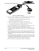
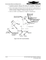
Figure 10-55.
FADEC Timing Tool
6.
Use a TDC locator to find TDC on Cyl #1. Mark the crankcase and propeller hub
with a grease pencil to indicate the position. Remove the TDC locator.
NOTE: Observe the FADEC Timing Tool LEDs; the N
c1
LEDs
should “blink” at approximately 11° BTDC.
7.
Slowly rotate the propeller clockwise while observing the tester LEDs.
a.
The N
c
LEDs will blink once in two propeller revolutions just before TDC.
b.
In two propeller revolutions, the N
e1
LEDs will blink 11 times.
8.
If the newly installed SSA fails to pass the operational check, troubleshoot the sensor
head. Refer to “Speed Sensor Assembly Troubleshooting” in Chapter 8.
9.
If the SSA passes the operational check, install the engine low voltage harness 25-pin
connectors according to instructions in section 10-11.1, ECU or SSA Connector
Installation.
10.
For proper operation of the engine, route, clamp, support, and protect the wires in the
engine low voltage harness in a manner to prevent chafing, fretting, and wear of the
lead wires. Route and secure the harness according to, “Harness Routing” instructions
in Appendix C.
11.
Clean, gap and install the spark plugs with new copper gaskets. Refer to “High
Voltage Harness and Spark Plug Maintenance” in Chapter 9 of this manual for spark
plug installation and high voltage harness connection instructions. Torque the spark
plug and high voltage harness according to Appendix B specifications.
12.
Perform a “FADEC Level I Diagnostics” in Chapter 8, Troubleshooting.


