2-6
IO-240 Series Engine Installation & Operation Manual
31 October 2011
Engine Description
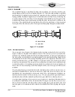
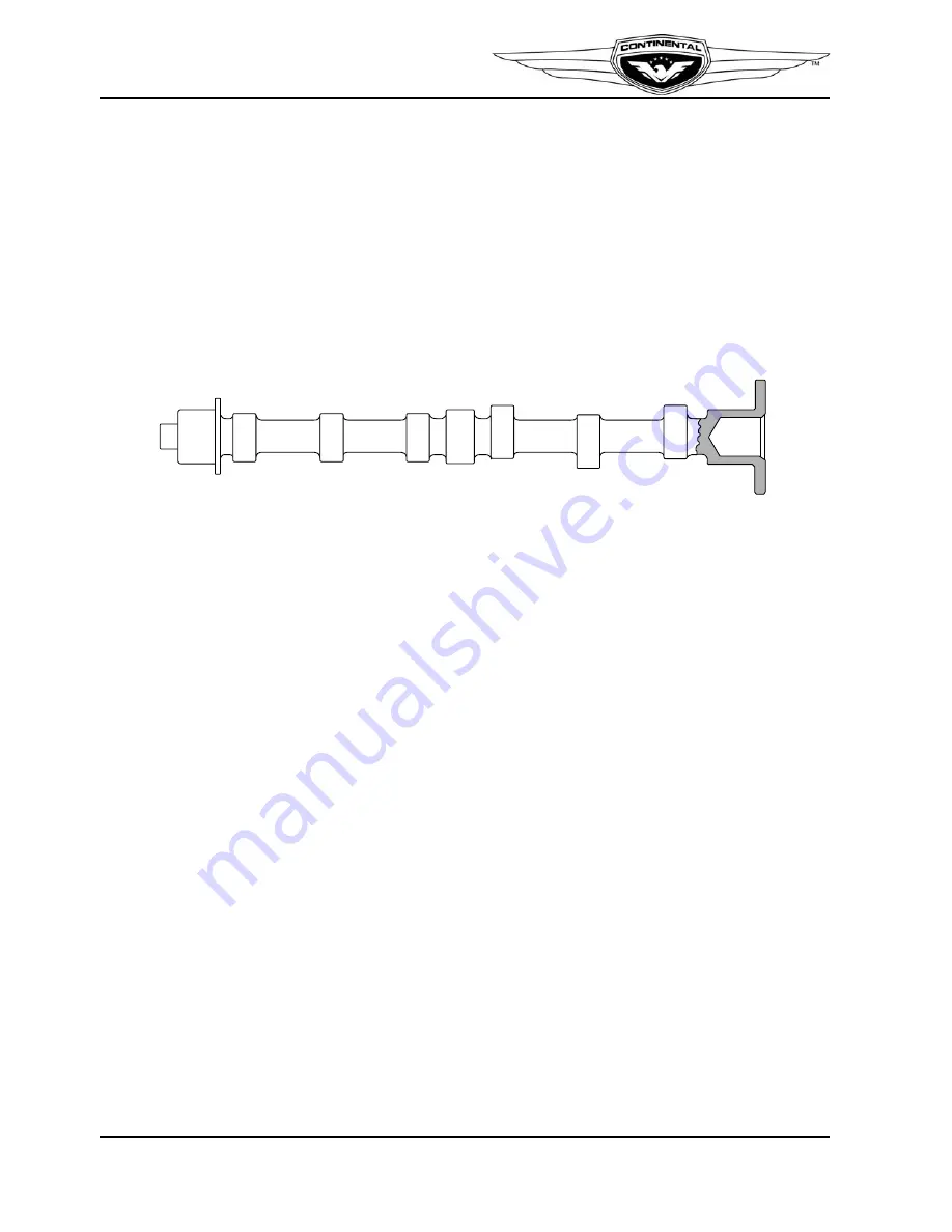
2-2.2.3. Camshaft
The camshaft forging is machined on three main journals, six cam lobes and the gear
mount flange at the rear of the camshaft (Figure 2-7). The lobes and journals are ground
and hardened. Camshaft main journals are supported in the crankcase by machined
bearing saddles. Hydraulic tappets move inward and outward in their bores, following the
eccentric shape of the cam lobes. Four unequally spaced bolts secure the gear to the
camshaft and ensure proper positioning, locating the gears' timing mark in relation to the
cam lobes. The camshaft gear has internal teeth to drive the alternator. A front-mounted
bevel gear drives the accessory drive bevel gear and fuel pump through a common shaft.
Figure 2-7. Camshaft
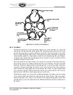
2-2.3. Accessory Case
The accessory case (Figure 2-8) aluminum alloy casting is attached to the rear of the
engine crankcase, aligned with crankcase dowels. The accessory case is secured to the
crankcase by crankcase studs and various attaching hardware. Accessory mount pads on
the rear surface are machined in one plane parallel to the machined parting flange which
surrounds the front side of the casting. Mounting pads for the magnetos, alternator cover,
starter, tachometer drive, oil filter adapter, oil pressure relief valve and an oil suction
screen boss are provided. The accessory case casting has two holes above and three studs
to attach the starter. A mounting pad is provided for a permanent oil screen housing. In
lieu of the oil screen housing, an oil filter adapter, with a screw-on type oil filter is also
available.
The oil pump housing is machined into the internal portion of the accessory case. A
machined, threaded boss is located on the lower right side of the accessory case for
installation of a non-adjustable oil pressure relief valve. Oil pump gear chambers are
machined in the interior of the accessory case. The oil pump drive gear shaft hole is
machined in-line with the camshaft and the driven gear shaft hole is directly above it.
A semicircular opening at the accessory case bottom is a machined threaded hole to
accommodate installation of the oil suction tube. Passages cast into the accessory case
allow oil to flow from the oil suction tube to the oil pump gears, pressure relief valve, and
main oil gallery. The tachometer drive shaft is the slotted end of the oil pump driven gear
shaft.
FRONT
REAR
#4 EXH
#3 EXH
#2 EXH
#1 EXH
#3 & 4
INTAKE
#1 & 2
INTAKE
M/J
C/L
C/L
C/L
C/L
C/L
C/L
M/J
M/J
C/L - CAM LOBE
M/J - MAIN JOURNAL
Содержание IO-240-A
Страница 145: ......
Страница 146: ...www continentalmotors aero ...


