2-4
IO-240 Series Engine Installation & Operation Manual
31 October 2011
Engine Description
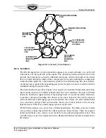
2-2.2. Engine Drive Train
The engine drive train (Figure 2-4) consists of the crankshaft, camshaft and drive gears.
The crankshaft has a propeller flange at one end to attach a propeller for thrust. The starter
gear meshes with the outer teeth of the rear crankshaft gear to turn the crankshaft until the
fuel mixture in the cylinder is ignited by the spark plugs. A drive gear at the rear end of the
crankshaft interfaces with a gear mounted on the rear end of the camshaft to synchronize
intake and exhaust valve movement and magneto rotation, as well as supply driving force
to the gear driven alternator. The oil pump driven gear, along with the optional tachometer
drive are gear driven by the inner row of teeth on the camshaft. The engine driven fuel
pump, and the optional vacuum pump drive are driven by a gear on the forward end of the
camshaft.
Figure 2-4. Engine Drive Train
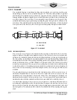
2-2.2.1. Crankshaft
The crankshaft (Figure 2-5) is an aircraft quality steel forging with three machined, main
journals supported by precision-bearing inserts in each of the three bearing saddles
machined in the crankcase. Four machined rod journals provide attachment of the
connecting rod assemblies.
The crankshaft gear is indexed on the crankshaft by a dowel and secured by machined
bolts. A neoprene oil seal over the crankshaft flange is seated between the crankcase
castings in the front shaft exit area, and is sealed to the crankshaft by a helical spring
inside the seal's cavity.
Starter
Alternator
Crankshaft
Camshaft
Fuel Pump &
Vacuum
Pump Drive
Shaft
Camshaft
Gear
Tachometer
Drive Shaft
Oil Pump
Drive Gear
Oil Pump
Driven Gear
Starter
Alternator
Crankshaft
Camshaft
Fuel Pump &
Vacuum
Pump Drive
Shaft
Camshaft
Gear
Tachometer
Drive Shaft
Oil Pump
Drive Gear
Oil Pump
Driven Gear
Содержание IO-240-A
Страница 145: ......
Страница 146: ...www continentalmotors aero ...


