2-12
IO-240 Series Engine Installation & Operation Manual
31 October 2011
Engine Description
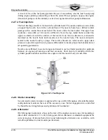
Figure 2-13. Oil Pump
2-2.5.2. Oil Sump
The oil sump body is a welded unit composed of front and rear halves of pressed sheet
steel. A thick mounting flange ring, an oil filler neck, and drain plug boss are welded to
the body to complete the assembly. The oil sump plug boss has provisions for safety
wiring the plug. A bracket welded to the neck attaches the oil sump to a stud in the lower
crankcase engine mounting arm. At the neck of the oil filler pipe, a locking device retains
the dip stick. The dipstick is marked in quarts to the full mark.
2-2.5.3. Oil Pressure Relief Valve
A machined, threaded boss is located on the lower right side of the accessory case for
installation of a non-adjustable oil pressure relief valve. Its passages are connected to the
oil pump outlet passage. This valve opens when the oil pump pressure exceeds the
specified operating limit and directs oil back to the oil sump.
2-2.5.4. Oil Cooler Adapter
The IO-240 engine features an oil cooler adapter (Figure 2-11) or oil cooler/filter adapter,
located on the lower 2-4 side crankcase. The IO-240-A (Figure 2-14) and B oil cooler
adapters (Figure 2-15 and Figure 2-16) function the same but differ physically. Each
incorporates a bypass valve in the event of a clogged oil cooler and have provisions for the
attachment of an externally-mounted oil cooler, with bosses for oil temperature and
pressure sensors. The oil cooler/filter adapter offers the same functions as the oil cooler
adapters with the added feature of a threaded boss for a spin on oil filter.
Содержание IO-240-A
Страница 145: ......
Страница 146: ...www continentalmotors aero ...


