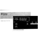

Contemporary Research 11
ICC2-ATSC 4S
Writing Your Own Control Code
While most IC systems use our Display Express software to control displays, a growing number of integrators are writing
their own control applications, using AMX, Crestron, RTI, or other platforms. We encourage creative solutions, and are
happy to support those who take advantage of our protocol.
From our history of support activity, we are providing a few tips to help you on your way.
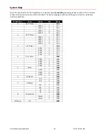
Device Numbers
iCC-Net devices are arranged with a zone structure, arranged in 15 groups of 256 devices. The first address in the group
represents the entire zone. For example, Zone 2’s group address is 512 (2*256). When a command is sent to 256,
all
controllers in that group will respond as one. An ALL command is 4095 (15,255, F FF in Hex)
–
all controllers will respond.
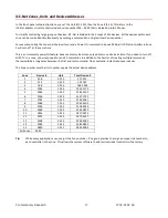
All commands follow the same structure of:
•
Attn = Hex A5
•
Zone = 1-15 (hex 1-F)
•
Unit = 1-255 (hex 1-FF)
•
Bytes = Number of bytes that follow
•
Command = 1 byte
•
Parameters = 1 to 4 bytes
String Format
Every software application has a different denotation for handling hex, ASCII, and decimal formats. The examples in this
manual are in AMX format, which is understood by many in the control industry:
•
Hex values begin with a dollar ($) symbol
•
ASCII values are enclosed in single quotes
•
Decimal values are shown as normal
If you plan on using a mixed-format structure for commands, convert the symbols to the types required by your software
application. For example, a
Tune Channel 2-3
command to device 260 could be shown several ways:
•
AMX Mixed Format = “$A5,1,4,5,’TH’,2,2,3”
•
AMX Hex Format “$A5 $01 $04 $05 $54 $48 $02 $02 $03”
•
Standard Hex (no denotation) = A5 01 04 05 54 48 02 02 03
•
Crestron Hex Format = \0xA5\0x01\0x04\0x05\0x54\0x48\0x02\0x02\0x03
•
RTI = Select port, Hex mode, enter A5 01 04 05 54 48 02 02 03 - note that when you go back to normal editing
mode, the app inserts an \x before each Hex character
Go to
www.asciitable.com
for a handy Decimal/ASCII/Hex conversion chart.