


5. Each component function
70
VPC-1600 User’s Manual
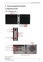
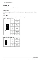
Reset swith
Push this button when resetting hardware.
Power swith
Push this button at power-on. In order to turn off the power forcibly, hold it down for four seconds or
longer.
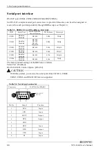
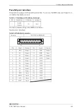
USB port
Eight USB interfaces are provided (USB2.0 : 4port, USB3.0 : 4port).
Table 5.9 USB 3.0 connector
Pin
Signal
USB3.0
1
USB_VCC
2
DATA-
3
DATA+
4
USB_GND
5
SSRX-
6
SSRX+
7
USB_GND
8
SSTX-
9
SSTX+
Table 5.10 USB 2.0 connector
Pin
Signal
USB2.0
1
USB_VCC
2
DATA-
3
DATA+
4
USB_GND
5
4
9
1
1
4
Содержание VPC-1600
Страница 1: ...FA Computer Space Saving Model VPC 1600 User s Manual CONTEC CO LTD...
Страница 15: ...1 Before Using the Product 8 VPC 1600 User s Manual...
Страница 21: ...2 System reference 14 VPC 1600 User s Manual...
Страница 49: ...3 Hardware setup 42 VPC 1600 User s Manual...
Страница 69: ...4 BIOS setup 62 VPC 1600 User s Manual...
Страница 97: ...6 Software RAID Setup 90 VPC 1600 User s Manual...
Страница 113: ...8 Appendix 106 VPC 1600 User s Manual...