Contec CONPROSYS nano CPSN-CNT-3201I Скачать руководство пользователя страница 30

  Installation 


CPSN-CNT-3201I Reference Manual (Hardware) 

  30 


Horizontal installation 


Make sure to gain proper space between the product and devices that generate heat or exhaust air 
so that the ambient temperature stays in the range specified in the environment requirement.   
Also, the temperature range in the environment requirements varies depending on the installation 
orientation, so check the operating temperature range in 

"Specifications (Page 39)"


Recommended installation angle 

The recommended installation angle for this product is 0°. The temperature specifications of the 
product vary between the case when the installation angle is 90° to the left/right and the horizontal 
installation is used, therefore check the operating temperature range in 

"Specifications (Page 39)"


Ambient temperature 

The ambient temperature is decided from the multiple measurement points which are a 50mm-
distance from the product. 
During the operation, adjust the air current to make certain that the temperatures measured in the 
points stay within the specified temperature. (-20 - +60°C) 


*As for the vertical installation with an angle of 90° to the right/left or the horizontal Installation, the 
ambient temperature should be -20 - +55°C. 


Содержание CONPROSYS nano CPSN-CNT-3201I

Страница 1: ...are CONTENTS Counter Module 32bit Counter Isolation CPSN CNT 3201I Introduction 4 Safety Precautions 10 Product Nomenclature and Function 16 Installation 28 Appendix 38 Optional Products 44 Customer S...

Страница 2: ...scription of Product Components 18 1 LED Indicator 18 2 Counter Input Connector 19 3 DIP Switch 20 3 Types and Operations of Pulse Signals 21 1 Types of Pulse Signals 21 2 Pulse Input 21 3 Multiplicat...

Страница 3: ...3 Table of Contents 3 The Details of Model Name 43 Optional Products 44 1 Optional Products 45 Customer Support and Inquiry 46 1 Services 47...

Страница 4: ...4 Introduction This section provides necessary information of the product such as the outline bundled items and manuals before actual use...

Страница 5: ...when operating the I O module with CPU Unit This describes the hardware aspects such as functions and settings of the I O module Download from the Contec website PDF CPU unit Reference Manual Hardware...

Страница 6: ...product visit our website to check the firmware version and update to the latest one if necessary Updating firmware to the latest version will resolve troubles and stabilize the operation Download ht...

Страница 7: ...counts input pulse signals from external devices to the CPU Unit of the CONPROSYS nano series It has one channel of 32 bit up down counters allowing external devices such as a rotary encoder and a li...

Страница 8: ...from carrying noise or a chattering All input terminals can be added a digital filter and the setting can be performed by software Output circuit include zener diodes for surge voltage protection Zene...

Страница 9: ...t The product consists of the items listed below Check with the following list that your package is complete If you discover damaged or missing items contact your retailer Product 1 10 pin Connector a...

Страница 10: ...10 Safety Precautions Understand the following definitions and precautions to use the product safely Never fail to read them before using the product...

Страница 11: ...Understand the meanings of these labels to operate the equipment safely DANGER DANGER indicates an imminently hazardous situation which if not avoided will result in death or serious injury WARNING WA...

Страница 12: ...r power medical equipment or other applications that require a very high level of reliability Do not use the product in such applications If using the product in applications where safety is critical...

Страница 13: ...of failure or abnormality foul smells or excessive heat generation unplug the power cables of the CPU unit immediately and contact your retailer Use a grounded shielded cable to connect with periphera...

Страница 14: ...are touched by someone s hands clean the terminals with industrial alcohol Always install the blank panels into vacant slots while power is active Use the product in accordance with the described ins...

Страница 15: ...ainst harmful interference when the equipment is operated in a commercial environment This equipment generates uses and can radiate radio frequency energy and if not installed and used in accordance w...

Страница 16: ...16 Product Nomenclature and Function This section describes product component names and their functions pin assignment of each connector...

Страница 17: ...ents Component names of the product are shown in the figure below No Name Function 1 LED Indicator This indicates status of the product 2 Counter Input Connector This is a connector for counter input...

Страница 18: ...as connectors switches are described 1 LED Indicator Status of the product is indicated by ON OFF and flashing of LED The meaning of each LED is described below Color and Description LED Color Displa...

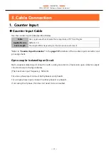
Страница 19: ...AH or equivalent Pin Assignment Pin No Signal Name Description 1 PCOM Positive common of input signal It connects the positive side of external power 2 PA For phase A input 3 PB For phase B input 4 PZ...

Страница 20: ...er The factory default of all switches are set to OFF SW Number Description 1 This switches phase A input resistance Turning on for 5 V Turning off for 12V 2 This switches phase B input resistance Tur...

Страница 21: ...with Gate Control Asynchronous Clear Multiply by 2 2 Pulse Input 2 phase Input Two phase pulse input consists of a phase A pulse advanced signal and a phase B delayed signal pulse that have 90 of pha...

Страница 22: ...incremental counting at the rising edges of negative pulses Single phase Input with Gate Control The counter can be started and stopped by using a gate control signal along with the single phase puls...

Страница 23: ...when count input multiplication is set During 2 Phase input During Single Phase input Single phase input is set only to multiply by 1 mode Multiply by 2 or any other higher setting is not available Si...

Страница 24: ...egative logic is used the signal is enabled while the phase Z input remains low Asynchronous Clear If a counter is set for CW clockwise direction Up count and phase Z positive logic whenever the phase...

Страница 25: ...fied by software Disable phase Z input Enable the next phase Z input only once Enable every phase Z input CAUTION If phase Z is set as negative logic a valid signal of phase Z input is low level If th...

Страница 26: ...e digital filter allows the counter to operate normally even when noise enters into pulses input to the counter and or into A B and Z phase signals Operation Principle The sampling clock cycle of the...

Страница 27: ...r set cycle clocks may occur depending on noise 3 One shot Pulse When the count value of a channel matches a preset compare value this channel will generate a one shot pulse Since the signal output se...

Страница 28: ...28 Installation This section describes how to mount the product on a DIN rail and to connect to an external device with a cable...

Страница 29: ...the product in the orientation shown below Other orientations may cause problems such as malfunctions due to inadequate heat dissipation Vertical installation Installation angle 0 Vertical installatio...

Страница 30: ...lation angle for this product is 0 The temperature specifications of the product vary between the case when the installation angle is 90 to the left right and the horizontal installation is used there...

Страница 31: ...nction may occur if there is other device generating high heat the radiation will influence the product to increase its temperature Do not install this product into the fully sealed space except the c...

Страница 32: ...onfirm the PWR LED is turned off before installing or removing the module Installing 1 Paying attention to the horizontal orientation of the I O module insert the resin groove into the rail of the CPU...

Страница 33: ...I Reference Manual Hardware 33 Removing 1 Press in the hooks at the top and bottom of the I O module and then pull it toward you and out of the CPU unit that has been installed on a DIN rail or that h...

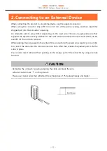
Страница 34: ...ay attention to the value that are combined current values of PA PB PZ and PDI for the common terminal While pushing the orange part in the center of the connector with a precision screwdriver or a si...

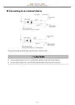
Страница 35: ...se environment Refer to Counter Input Connector in the page 19 for details of the counter input connector and pin assignment Opto coupler Isolated Input Circuit Opto coupler isolated input connection...

Страница 36: ...ting to an external device The general purpose input signals use the same circuit structure CAUTION To use external power 5V turn on all the DIP switches on the side of the product To use external pow...

Страница 37: ...e Connection with a Linear Scale One shot Pulse Output Connection When the count value of each channel and the user set value match the circuit outputs a matched signal for one shot 1 pulse The pulse...

Страница 38: ...38 Appendix This section lists the specifications and the physical dimensions of the product and the details of model name...

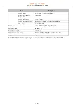
Страница 39: ...urrent 12mA or more Input OFF current 0 8mA or less Response frequency 500kHz duty 50 Max Interrupt level One interrupt caused upon channel count match or timer time out External power 1 5V 5 or 12VDC...

Страница 40: ...0 104 45msec Output protection circuit Zener diode CMZB47 Toshiba or equivalence External power 5V 12VDC 10 Connector 2 pieces 3 81mm pitch 10 pin terminal Applicable wire AWG28 16 Current consumptio...

Страница 41: ...stance Line noise Signal Line 1kV IEC61000 4 4 Level 3 EN61000 4 4 Level 3 Static electricity resistance Touch 4kV IEC61000 4 2 Level 2 EN61000 4 2 Level 2 Air 8kV IEC61000 4 2 Level 3 EN61000 4 2 Lev...

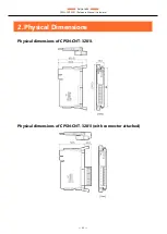
Страница 42: ...Appendix CPSN CNT 3201I Reference Manual Hardware 42 2 Physical Dimensions Physical dimensions of CPSN CNT 3201I Physical dimensions of CPSN CNT 3201I with connector attached...

Страница 43: ...I Reference Manual Hardware 43 3 The Details of Model Name Details of the model name are described below No Item Description 1 Interface CNT Counter 2 Resolution 32 32 bit 3 Channel 01 1 Channel 4 Iso...

Страница 44: ...44 Optional Products This section lists optional items that can be used along with the product...

Страница 45: ...ion CPU unit CPSN MCB271 S1 041 Remote I O CPU unit CPSN MCB271 1 041 Remote I O CPU unit LAN HUB model DIN rail fitting power supply CPS PWD 30AW24 01 Fitting power supply 30W Input 100 240VAC Output...

Страница 46: ...46 Customer Support and Inquiry CONTEC provides the following support services for you to use CONTEC products more efficiently and comfortably...

Страница 47: ...the useful information including product manuals that can be downloaded through the CONTEC website Download https www contec com download You can download updated driver software firmware and differen...

Страница 48: ...Revision History CPSN CNT 3201I Reference Manual Hardware 48 Revision History MONTH YEAR Summary of Changes April 2020 The First Edition...

Страница 49: ...5 0025 Japan https www contec com No part of this document may be copied or reproduced in any form by any means without prior written consent of CONTEC CO LTD CPSN CNT 3201I Reference Manual Hardware...

Отзывы: