Setup
CNT24-4(PCI)
10
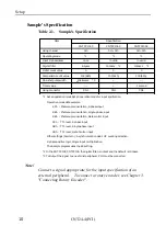
Sample's Specification
Table 2.1. Sample's Specification
Item
Specification
CNTPCI01.C
CNTPCI02.C
CNTPCI03.C
Using channel
0ch
0ch - 3ch
0ch - 3ch
Operating mode
*1
*1
*1
Input Z-phase/clear
once
in valid
in valid
Digital filter
6.5
µ
sec
100nsec *2
100nsec *2
Initial count value
0
0
0
Comparison count value
100 (64h)
100 (64h)
100 (64h)
One-shot pulse width
≠
104.4msec *3
---
---
Timer value
---
---
1 second
Using connector
CN1
CN1
CN1
*1 Set an operation mode Set an operation mode for input spcification.
Operation mode data example
8Ch : Photocoupler insulation, 2-phase input
9Bh : Photocoupler insulation, Single-phase input
8Bh : Photocoupler insulation, Gate control input
CCh : TTL level, 2-phase input
DBh : TTL level, Single-phase input
CBh : TTL level, Gate Control input
Other settings (Common) : Asynchronization clear, UP counting direction,
Z-phase positive logic, Single input multiplication.
The Sample program uses the 8C setting.
*2 In the CNTPCI02, CNTPCI03, the digital filter is not set and the default is 100nsec.
*3 To Output the signal to an external peripheral, CN1 must be connected.
Note!
Connect a signal appropriate for the input specification of an
external peripheral. To connect a rotary encoder, see Chapter 3.
"Connecting Rotary Encoder".
Содержание CNT24-4
Страница 1: ...CNT24 4 PCI 24Bit Up Down Counter Board for PCI User s Guide ...
Страница 13: ...Introduction CNT24 4 PCI 4 ...
Страница 41: ...External Connection CNT24 4 PCI 32 ...
Страница 67: ...I O Ports and Registers CNT24 4 PCI 58 ...
Страница 75: ...A 41 781 LZC6961 000707 971007 ...


