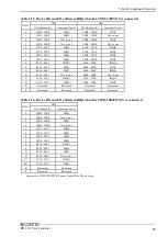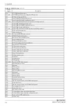
5. Each Component Function
BX-320 User’s manual
57
Component Function
LED: POWER, ACCESS, L1, L2
There are 4 LED in front of this product.
Table 5.2. Display Contents of LED
LED name
State
Display contents
POWER LED
OFF
Indicates that this product is switched off.
ON (Green)
Indicates that this product is switched on.
ACCESS LED
ON (Red)
Indicates that the SATA device is being accessed.
L1(USER LED)
OFF
When I/O port 8800H bit 0 is set to "0", the LED turns off. When set to "1",
the LED turns on. Readable.
ON(Red)
L2(USER LED)
OFF
When I/O port 8801H bit 0 is set to "0", the LED turns off. When set to "1",
the LED turns on. Readable.
ON (Green)
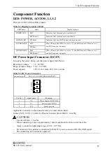
DC Power Input Connector: DC-IN
To supply the power, always use the power supply listed below.
Rated input voltage
: 12 - 24VDC
Range of input voltage : 10.8 - 31.2VDC
Power capacity
: 12V 4.2A or more, 24V 2.2A or more
Table 5.3. DC Power Connector
Connector type
MC1,5/3-G-3,5(PHOENIX CONTACT)
Pin No.
Signal name
Meaning
1
Vi+
Power supply (12-24VDC)
2
Vi-
Power supply (GND)
3
FG
Frame ground
Applicable connector on the connector side (provided with module)
Contact: MC1,5/3-ST-3,5 (mfd. by Phoenix Contact) [For AWG28 - 16 cable]
-
Use the AWG24 - 16 cable.
-
When connecting, remove approximately 7mm of insulation from the end of the cable.
-
Apply a conductor tightening torque of 0.22 - 0.25 Nm.
-
FG terminal of this product is conducted with the DC power connector (DC-IN) GND signal.
-
The conducting state cannot be separated.
CAUTION
Содержание BX-320-DC700000
Страница 1: ...IPC Series BOX PC for BX 320 Series User s Manual CONTEC CO LTD...
Страница 7: ...vi BX 320 User s manual...
Страница 21: ...2 System Reference 14 BX 320 User s manual...
Страница 61: ...4 BIOS Setup 54 BX 320 User s manual...
Страница 77: ...5 Each Component Function 70 BX 320 User s manual...
Страница 95: ...6 Appendix 88 BX 320 User s manual...

