6
Specifications
Why can’t I get 11Mb/sec thruput like those other guys advertise?
The truth is that
all 802.11b devices on the market operate in half duplex mode which cuts the realistic
thruput in half so theoretical maximum is 5.5Mb/sec. Because of 128bit encryption and
other communication overhead within the devices, typical thruput maximums are 4.0 to
4.5Mb/sec. We believe in only advertising tested and verified
actual
thruput numbers
so you get what you expect and not some pie-in-the-sky empty promise. Refer to the
chart above for actual thruput vs distance test results.
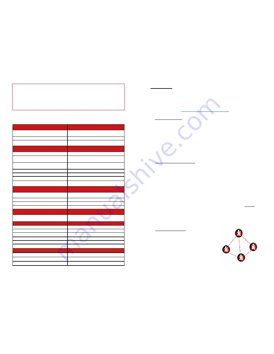
General
Standards
802.11b (Wlan), 802.3(LAN), 802.3af
(POE)
Modulation
DSSS (DPBSK, DQPSK, CCK)
Certifications
FCC / CE
Radio Specifications
Operating Frequency
2400 to 2497MHz
Channels
USA/Canada 11; Japan 14; France 4;
Europe 13
RF Output Power
(software selectable)
250mW, 200mW, 150mW, 100mW
Maximum EIRP
+38dBm
Receive Sensitivity @ 11Mbps
-87dBm
Security
64/128bit WEP, WPA or TKIP 802.1x
Remote Config (Web Based)
By IP Address; thru Wireless or Ethernet
Antenna Specifications
Antenna Gain
14 dBi
Antenna Beamwidth (V & H)
35 deg
Antenna Front to Back
>18dB
Polarization
Horizontal or Vertical
POE Specification
Power Over Ethernet Injector (CE
Approved / 802.3af Compliant)
INPUT: 90 – 264VAC @ 47 – 63Hz OUT-
PUT: 48VDC @ .35A
Mechanical Specifications
Color
White or Gray
Dimensions (L x W x H)
10.75” x 10.75” x 2.6” (267 x 267 x 67mm)
Weight
29 oz (800 g)
Ethernet Connector
Field Replaceable Waterproof RJ45
Cable (75’ long)
CAT5E Outdoor Rated Shielded Cable
Mount
Wall or Pole Mount
Environmental Specifications
Operating Temperature
-40 to 167 Deg F (-40 to 75 Deg C)
Humidity
0 to 100% RH
Wind Loading (125MPH survivability)
100MPH / 28lbs; 125MPH / 43lbs
9
TECH NOTE:
You may want to play around with different settings to
see what works best for your particular link. The measurement you
would use to compare settings would be to measure the actual thruput
by timing the transfer of data across the link. One program that we have
found useful for determining thruput is DISKBENCH
(
http://nodesoft.com/DiskBench/
).
6.
SITE SURVEY:
The site survey is a very useful tool to determine
what wireless devices are within range of your
Q-Bridge
TM
. Goto
WIRELESS | SITE SURVEY and click on REFRESH. The list will show
all wireless devices including the remote
Q-Bridge
TM
unit (The remote
unit will have a blank SSID, for additional security, but can be identified
by its MAC address). The table will show channel #, MAC Address and
relative signal strength of all the devices within the range of the
Q-
Bridge
TM
. This is useful to see where possible interference could be
coming from in case you are experiencing performance problems.
7.
ANTENNA ALIGNMENT:
Because of the special antenna design,
antenna alignment is simple using just visual alignment and an elec-
tronic alignment isn’t necessary. If you’d like to use the antenna align-
ment tool, make sure that both sides of the link are attached to an ac-
tive network, then goto WIRELESS | ANTENNA ALIGNMENT | ENTER
ANTENNA ALIGNMENT MODE then click on Antenna Alignment Me-
ter. This will bring up a bar graph display showing RSSI (signal
strength) and SQ (signal quality). It’s normal for these numbers to
bounce around a bit but they are useful to get an average reading. You
can move the antenna while watching the numbers to get a peak signal.
Due to terrain variances and reflections this peak signal might cause
the antenna to be tilted away slightly from visual alignment. NOTE: Af-
ter antenna alignment both sides of the link will need to be rebooted.
This can be accomplished by unplugging the POE power supply and re-
plugging it in or if you have computer access to the unit by clicking on
the reboot button on the STATUS page.
8.
MESH NETWORK:
You can add an
additional 2
Q-Bridge
TM
units to create a
mini mesh network. This is useful if you
want to connect 4 buildings together. All
Q-Bridge
TM
units must have the same
settings for Encryption and Channel.
Each unit must have a unique IP address.
To add another
Q-Bridge
TM
you will
need to add the MAC addresses of any
SAMPLE MESH NETWORK


