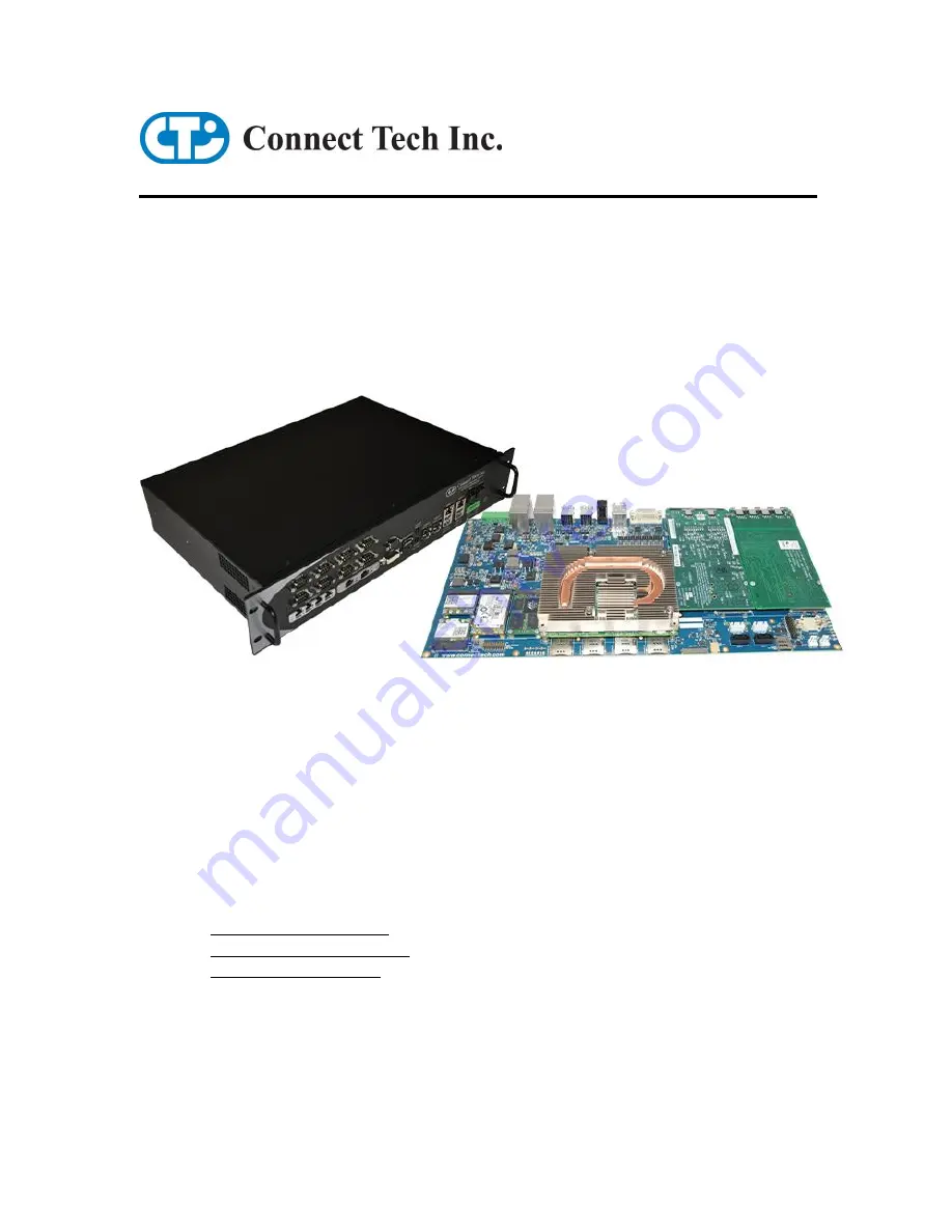
background image


COM Express Type 6  

PMC/XMC Carrier  

Users Guide


Connect Tech Inc. 
42 Arrow Road 
Guelph, Ontario 
N1K 1S6 
 

Tel: 

519-836-1291 

Toll:


800-426-8979 (North America only) 

Fax:


519-836-4878 

Email: 

[email protected]  


[email protected]  

Web: 

www.connecttech.com  


CTIM-00115 Revision: 0.03, July 12, 2017

Содержание COM Express 6

Страница 1: ...Guide Connect Tech Inc 42 Arrow Road Guelph Ontario N1K 1S6 Tel 519 836 1291 Toll 800 426 8979 North America only Fax 519 836 4878 Email sales connecttech com support connecttech com Web www connecttech com CTIM 00115 Revision 0 03 July 12 2017 ...

Страница 2: ...ctor 12 Input Power 13 Input Power Diagram 13 Active Input Power Protection Details 14 Input Power Connector Details 14 Video Outputs 15 HDMI and Display Port 15 DVI 16 LVDS Video 17 Description 17 LVDS Video Header 17 LVDS Backlight Power Connector 18 LVDS Backlight Power Jumper 18 LVDS Panel LEDADJ Selection Jumper 19 VGA 19 VGA Pinouts 19 USB 3 0 20 Connector 20 10 100 1000 Ethernet 21 10 100 1...

Страница 3: ...rial Connectors RS 232 RS 485 Pinout 28 Pinout Mapping on PCB 0 1 Headers 29 8 x Serial Port Jumper Configuration 29 8 x Serial Port Cabling Details 30 PMC XMC Expansion Slots 31 GPIO and Console Serial Port 32 Connector 32 SD Card 33 Micro SD Card Connector 33 System Control Header 34 Typical Hardware Installation Procedure 35 On Board ATX Power Supply 36 Current Consumption Details 37 PCI Expres...

Страница 4: ...l support is always free Contact Information Mail Courier Connect Tech Inc Technical Support 42 Arrow Road Guelph Ontario Canada N1K 1S6 Email Internet sales connecttech com support connecttech com www connecttech com Note Please go to the Download Zone or the Knowledge Database in the Support Center on the Connect Tech website for product manuals installation guides device driver software and tec...

Страница 5: ...able or to retract the Warranty if no replacement is available The above warranty is the only warranty authorized by Connect Tech Inc Under no circumstances will Connect Tech Inc be liable in any way for any damages including any lost profits lost savings or other incidental or consequential damages arising out of the use of or inability to use such product Copyright Notice The information contain...

Страница 6: ...ations ESD Warning Electronic components and circuits are sensitive to ElectroStatic Discharge ESD When handling any circuit board assemblies including Connect Tech COM Express carrier assemblies it is recommended that ESD safety precautions be observed ESD safe best practices include but are not limited to Leaving circuit boards in their antistatic packaging until they are ready to be installed U...

Страница 7: ...reo Input 1 Stereo Output PMC XMC Slots 2 Dual mode mSATA MiniPCIe 2 MiniPCIe Only Slots 2 SIM Card Slots 4 USB 3 0 Ports 4 USB 2 0 Ports 6 SATA HDD connector 2 SATA HDD power connector 2 GPIO or Micro SD Y 1 Power Connector 4 Position screw terminal Standard Serial 8 x RS 232 485 1 Console Serial Port 1x RS232 basic port 1 CMOS RTC 3 3V Battery Y Accessories Optional Cable Kit SATA HDD Power Cabl...

Страница 8: ... 82574L HD Audio Codec Cirrus Logic CS4207 PCIe UART Exar 17V354 On Board ATX Compliant PSU HDMI USB 2 0 Port 0 USB 2 0 Port 1 USB 2 0 Port 2 USB 2 0 Port 3 VGA LVDS USB 2 0 Port 4 USB 2 0 Port 5 mSATA mini PCIe Slot 0 mini PCIe Slot 2 mini PCIe Slot 3 SIM Card Socket SIM Card Socket SIM Card Socket SIM Card Socket PCIe x1 PLX 8112 PCIe to PCI Bridge PMC XMC Slot 0 PMC XMC Slot 1 PCIe x8 PCIe x8 P...

Страница 9: ...Connect Tech COM Express Type 6 PMC XMC Carrier Board User Manual Revision 0 03 9 Connector Locations Top View Front View ...

Страница 10: ...CIe Slot 2 SIM Card Socket P9B SIM Card Socket miniPCIe Slot 3 SIM Card Socket P10A SIM Card Socket miniPCIe Slot 0 SIM Card Socket P10B SIM Card Socket miniPCIe Slot 1 SIM Card Socket P11 2 x 20 pin 0 1 header RS 232 485 PORTS 1 4 P12 2 x 20 pin 0 1 header RS 232 485 PORTS 5 8 P13 2 x 5 pin 2mm header VGA Video Connector P14 2 x 10 pin 2mm header GPIO RS 232 Console Connector P16 4 pin 5mm Pitch ...

Страница 11: ...Port 6 Settings J1G 7 position 2mm Jumper Block RS 232 RS 485 Port 7 Settings J1H 7 position 2mm Jumper Block RS 232 RS 485 Port 8 Settings J3 2 x 2 2mm Jumper Block LVDS Backlight Power Enable J4 1 x 3 2mm Jumper Block LVDS Backlight Control Enable J6A 2mm Jumper miniPCIe mSATA Slot 0 Selection J6B 2mm Jumper miniPCIe mSATA Slot 1 Selection J7 2mm Jumper PCIe UART EEPROM Enable J8 2mm Jumper PCIe...

Страница 12: ...on the COM Express Type 6 CPU module which connects to the COM Express carrier via a Tyco fine pitch stacking connector Function COM Express interface Location P1 Type Tyco fine pitch stacking connector Part Number 3 5353652 6 8mm stack height Pinout Refer to COM Express R2 0 specification Type 6 CPU Fan Connector Function Fan Power Location P18 Type Molex 22 23 2031 Pinout Pin Signal 1 Fan Tach 2...

Страница 13: ...wer source in the rage of 6V to 36V DC which is ideal for many vehicle or rugged applications but also many industrial power solutions as well Input Power Diagram Below is diagram of the flow of the input power on the COM Express Type 6 PMC XMC Carrier The input power goes through various protection safety and filtering components before connecting to the main on board regulators ...

Страница 14: ...er fault condition a timer is started inversely proportional to MOSFET stress If a fault condition persists the supply is turned off Two precision comparators monitor the input supply for overvoltage OV and undervoltage UV conditions When the potential is below the UV threshold the external MOSFET is kept off If the input supply voltage is above the OV threshold the MOSFET is not allowed to turn b...

Страница 15: ...s interfaces depends on your Type 6 COM Express module The configuration of either interface as the primary or secondary or tertiary display depends on the COM Express module s BIOS capabilities and settings Refer to the COM Express module s documentation for more details HDMI and Display Port Function HDMI and Display Port Location P3 Type DisplayPort Standard 4 lane connection HDMI Standard 3 pa...

Страница 16: ... pixel clock No dual link signals are routed to this DVI Connector No analog signals are routed to this DVI Connector Function HDMI and Display Port Location P3 Type Pin Signal 1 TMDS Data Channel 2 2 TMDS Data Channel 2 3 Shield for TMDS Data 2 4 4 NC 5 NC 6 DDC Clock 7 DDC Data 8 NC 9 TMDS Data Channel 1 10 TMDS Data Channel 1 11 Shield for TMDS Data 1 3 12 NC 13 NC 14 Power 5V 15 Ground 16 Hot ...

Страница 17: ... Header Function LVDS Graphics Location P13 Type Hirose DF19G 20P 1H 54 connector Pinout Pin Signal Description 1 3 3 VCC_PNL Panel Power 2 3 3 VCC_PNL Panel Power 3 GND Digital ground 4 GND Digital ground 5 LVDS_A0_N Channel A Data 6 LVDS_A0_P Channel A Data 7 GND Digital ground 8 LVDS_A1_N Channel A Data 9 LVDS_A1_P Channel A Data 10 GND Digital ground 11 LVDS_A2_N Channel A Data 12 LVDS_A2_P Ch...

Страница 18: ...hite LED has a Vf of around 3 3V Location P7 Type JST SM02B BHSS 1 TB LF SN connector Pinout Pin Signal 1 VA LED 2 VK LED LVDS Backlight Power Jumper Function LVDS backlight power select You can optionally connect 5V to pins 17 18 of the LVDS Video connector Some LVDS displays require this for backlight powering others require external backlight power to be sourced from P7 Location J3 Type 2x2 2mm...

Страница 19: ...B Enable Control Default Off or position A VGA The carrier boards brings the VGA video output to a 2x5 2mm header This header can be mated to Connect Tech s CBG070 cable which then terminates to a standard DB 15 VGA connector which is panel mountable VGA Pinouts Function Standard VGA Location P11 Type 2x5 2mm pitch header Pinout Pin Description 1 Red 2 GND 3 Green 4 NC 5 Blue 6 SC DDC 7 HSYNC 8 SD...

Страница 20: ...o USB connectors Over current protection power supply filtering and ESD protection is provided Each USB 3 0 port is capable of bitrates of up to 5Gbps as well as accepting USB2 0 and below connections Connector Function USB 3 0 Locations P21A P21B Type Standard Dual USB 3 0 jacks Pinout Pin Description 1 VBUS 2 D 3 D 4 GND 5 SSRX 6 SSRX 7 GND 8 SSTX 9 SSTX ...

Страница 21: ...unction LAN Connector Locations P21A P21B Type Standard 8 position RJ connector Pinout Pin Signal 1 MX1P 2 MX1N 3 MX2P 6 MX2N 4 MX3P 5 MX3N 7 MX4P 8 MX4N Software Support for the Intel 82574 Additional drivers will be needed to properly operate the GBE Port 0 on the COM Express carrier These drivers can be downloaded directly from Intel website from the below link http downloadcenter intel com Sea...

Страница 22: ...eader can be mated to any standardized motherboard type dual USB to panel cabling As well USB 2 0 connections are also routed to the miniPCIe slots USB 2 0 External Connectors Function USB 2 0 Locations P23A P23B Type Standard Dual USB 2 0 jacks Pinout Pin Description 1 VBUS 5V 2 D 3 D 4 Ground USB 2 0 Internal Connector Function USB 2 0 Locations P2A P2B Type Standard 10 pin ATX Style DIL Header ...

Страница 23: ...eo Jacks Notes 1 The Microphone input is equipped with a Phantom Power circuit 2 The Headphone output is amplified by the CS4207 Codec Some operating systems may not properly register the input sense detection from the CS4207 audio codec Software Support for the CS4207 Additional drivers will be needed to properly operate audio on the COM Express carrier Some downloadable links can be found below ...

Страница 24: ... Pin Signal 1 GND 2 SATA_TX_P 3 SATA_TX_N 4 GND 5 SATA_RX_N 6 SATA_RX_P 7 GND SATA HDD Power Connectors Function SATA HDD Power Locations P6 P7 Type 4 Pos 0 100 connector Can be mated to any 0 1 cable assembly or Connect Tech s CBG090 cable which ships in the CCG008 cable kit Pinout Pin Signal 1 GND Black 2 5V Red 3 GND Black 4 12V Yellow 12V and 5V are protected with 1200mA Raychem Poly fuses Not...

Страница 25: ...TA slots Each of the special dual purpose slots can accept either a mini PCIe module or a mSATA SSD module These slots have special circuitry that allows for the selection between connecting PCIe lanes or SATA lanes Each slot is also provided with a USB 2 0 in addition to the PCIe as per the mini PCIe specification see below for a block diagram of the slots functionality Standard miniPCIe Slot Blo...

Страница 26: ...Half and Full Length mini PCIe mSATA module Installation The COM Express Type 6 PMC XMC Carrier s miniPCIe mSATA slots are designed for easy ruggedized selection between full and half length modules This is done via the installation of M2 5 threaded standoffs Standoffs and screws are provided with the shipping configuration of the carrier board Below are some examples of how the various modules si...

Страница 27: ...1 SATA RX From Host System 32 NC 33 SATA RX From Host System 34 GND 35 GND 36 NC 37 GND 38 NC 39 3 3V 40 GND 41 3 3V 42 NC 43 RESV 44 NC 45 NC 46 NC 47 NC 48 1 5V 49 NC 50 GND 51 NC 52 3 3V miniPCIe Pinout Pin Number Description 1 NC 2 3 3V 3 NC 4 GND 5 NC 6 1 5V 7 CLKREQ 8 UIM_PWR 9 GND 10 UIM_DATA 11 PCIe CLK 12 UIM_CLK 13 PCIe CLK 14 UIM_RESET 15 GND 16 UIM_VPP 17 NC 18 GND 19 NC 20 W_DISABLE 2...

Страница 28: ...Input CTS Input 3 RxD Input RxD Input 4 RTS Output RTS Output 5 TxD Output TxD Output 6 CTS Input CTS Input 7 DTR Output TxD Output 8 RI Input RTS Output 9 SG Signal Ground SR Signal Reference 10 N C No Connection N C No Connection 2 or 6 11 DCD Input RxD Input 12 DSR Input CTS Input 13 RxD Input RxD Input 14 RTS Output RTS Output 15 TxD Output TxD Output 16 CTS Input CTS Input 17 DTR Output TxD O...

Страница 29: ...t Jumper Configuration The COM Express Type 6 PMC XMC Carrier allows for each of its 8 external serial ports interface to be hardware configurable The four most desired modes are RS 232 RS 485 Full Duplex 4 wire RS 485 Half Duplex 2 wire and RS 485 Multi Drop Slave Details on how to configure each of these modes can be found below ...

Страница 30: ...mountable The cable is shown below as well as details on the pinouts of the DB 9 end connectors CAG8104 Cable CAG8104 DB 9 Connector Pinout Pin RS 232 RS 422 485 DB 9 Signal Direction Signal Direction 1 DCD Input RxD Input 2 RxD Input RxD Input 3 TxD Output TxD Output 4 DTR Output TxD Output 5 SG Signal Ground SR Signal Reference 6 DSR Input CTS Input 7 RTS Output RTS Output 8 CTS Input CTS Input ...

Страница 31: ...ion In order to properly use both PMC XMC expansion slots your modules BIOS must configure its PEG link to be configured as 2 x8 PCIe links Some modules allow this configuration to be done via the BIOS settings other require a special utility to be run for configuration Please consult with your COM Express modules Manual for full details on configuring the COM Express PEG as split x8 PCIe links Fu...

Страница 32: ...ctionality of COM Express Type 6 specification Connector Function Console RS 232 GPIO Locations P9 Type 2x10 2mm Header Pinout Header Pin Signal DB9 Pin 1 GPIO Input 0 1 2 GPIO Output 3 6 3 GPIO Input 1 2 4 GPIO Output 2 7 5 GPIO Input 2 3 6 GPIO Output 1 8 7 GPIO Input 3 4 8 GPIO Output 0 9 9 GND 5 10 11 1 12 6 13 RS 232 TX 2 14 RS 232 RX 7 15 3 16 8 17 4 18 9 19 GND 5 20 ...

Страница 33: ...er the GPIO pins See below for the SDIO GPIO mapping SD Card Jumpers J9 Will enable disable SDIO GPIO Functionality JUMPER ON SD Enabled JUMPER OFF GPIO J10 Will enable disable Write Protect on the SD Card JUMPER ON Write Protect Enabled JUMPER OFF Write Protect Disabled Micro SD Card Connector Function Micro SD Card Slot Locations P4 Part Number 502570 0893 Type Micro SD Card Socket Pinout Pin SD...

Страница 34: ...wer button reset button PC speaker I2C device and monitor other power rails Function Miscellaneous Control Header Location P19 Type 2x10 0 1 Pinout Pin Description Pin Description 1 Speaker 2 Speaker 3 5V 4 5VSB 5 Ext CMOS Bat 6 GND 7 System Reset 8 GND 9 Power Button 10 GND 11 Batlow 12 GND 13 Sus_S3 14 GND 15 I2C CLK 16 GND 17 I2C DAT 18 GND 19 5V 20 GND ...

Страница 35: ...ny other cooling instructions from the manufacturer 3 Install the necessary cables for the application At a minimum this would include a Power cable to the input power connector b Connect a video display cable to one of the video channels c Keyboard and mouse via USB d SATA Power and Signal to SATA HDD For the relevant cables see the Cables Interconnect section of this manual 4 Connect the power c...

Страница 36: ...al for shutdown The main power rails can be powered ON and OFF via the power button pins located on the system control header The voltages generated by the on board supply are 12V 5V 3 3V 1 8V 1 5V 5V SB and 3 3V SB Below is a listing of the current sourcing capabilities of the on board power supplies Power Rail Maximum Current Sourcing Capability 12V 10A 5V 10A 3 3V 10A 1 8V 0 15A 1 5V 5A 5V SB 1...

Страница 37: ...Express module is installed please refer to the module manufactures manual for full details on the current consumption of the particular module you are using Actual Measurements Amps Watts Carrier standalone no module installed powered ON with no loads TBD TBD Module Installed 1 single DDI video output USB keyboard with system sitting in BIOS TBD TBD Module Installed 1 single DDI video output USB ...

Страница 38: ...se note that if you are intending to use the USB ports to their maximum bandwidth that you should be selecting ports that are directly connected to the COM Express USB ports and not through the USB hub controller IE For highest USB bandwidth select ports from the table below on the left COM Express USB Port Peripherial Connection Port 0 USB 3 0 USB Port 0 External Port 1 USB 3 0 USB Port 1 Externa...

Страница 39: ...on 0 03 39 Mechanical Details A complete 3D STEP Model file of carrier board can be downloaded here http www connecttech com ftp 3d_models CCG007_3D_MODEL zip 2D Mechanical Dimensioned Drawing All dimensions are in mm TBD Mounting Holes Details All dimensions are in mm TBD ...

Страница 40: ... to fit into a 19 width rack mount enclosure Connect Tech also offers a standardized 2U off the shelf enclosure that is specifically designed to fit the carrier board and all of its peripherals Details on this can be found below For ordering and pricing details on this enclosure please contact sales connecttech com Front Panel View Isometric View Mechanical Details ...

Страница 41: ... kit CKG009 PCB Connector Cable Part Number Description PCB End Interface End 40 Pin 0 1 Pitch Header at P11 P12 CAG8104 8 x Serial Cable 2x20 pin 0 1 header 8 x DB9 Male 2x10 2mm at P8 P9 and P10 CBG073 2 x Serial Cable Also used for GPIO 2x10 2mm header 2 x DB9 Male SATA Power and Signal at P2A B P3A B CBG090 SATA Power and Signal SATA Power and Signal SATA Power and Signal 2x5 2mm at P26 CBG070...

Отзывы: