


Copyright
©
2017
congatec
GmbH
PA50m112
39/48
6
Additional Features
6.1
Feature Connectors and Micro-SD Card Slot
The conga-PA5 provides three feature connectors and a micro-SD card slot.
6.1.1
Buttons and LEDs
The conga-PA5 offers lid, sleep, reset, power buttons as well as LED signals via the feature connector X18.
Table 24 X18 Pinout Description
Pin
Signal Name
Description
Comments
1
LID_BTN#
Active-low signal brings the system into sleep state or wakes
it up.
Requires an ACPI compatible operating system.
2
GND
Ground
3
SLP_BTN#
Active-low signal triggers sleep state.
4
GND
Ground
5
RST_BTN#
Active-low signal triggers hard reset.
Does not keep the system in reset when connected to ground.
6
GND
Ground
7
PWR_BTN#
Active-low signal triggers power-up sequence. Pulse duration
of ≥ 4 seconds triggers forced shutdown.
Signal can also be triggered by the cBC depending on BIOS
settings (see section 6.2.2 "Power Loss Control").
8
GND
Ground
9
PWR_LED (anode)
LED is on if the system is powered on.
10
GND (cathode)
LED is on if the system is powered on.
11
SATA_LED (anode)
LED indicates activity on the SATA port CN1 and/or mSATA.
12
SATA_ACT# (cathode) LED indicates activity on the SATA port CN1 and/or mSATA.
Connector Type
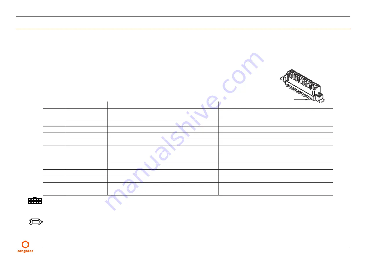
X18: 12x1 pins, 1.25 mm pitch (Molex 53398-1271); Possible Mating Connector: Molex 51021-1200
Note
1.
The LEDs on the conga-PA5 are supplied by +3.3 V with 330Ohm series resistors. You can connect X18 pins directly to the LED terminals.
2.
The buttons are edge triggered with 16 ms debouncing and can be directly connected to a tactile switch or OC output.
Pin 1
X18


