background image

18

!CAUTION:  Use the relief valve pressure only as a backup to the electronic tension 

control system or other load limiting means.  Damage to the cable being installed 

may result.

1. Set up the puller as if cable were to be pulled, including installation of the capstan (fig-

ure 21).

2. Place a pull line around the capstan.  The pull strength of the pull line must exceed the 

2,000 pound maximum capacity of the Fiber Optic Cable Puller.

3. Attach the pull line to a load indicator such as a Dillion dynamometer (section 14).

4. Release the lock nut on the relief valve (figure 22).  Turn the relief valve stem counter-

clockwise to adjust the valve down to zero pressure.

5. Slowly apply pressure to the puller to tighten the pull line. Continue to pull until the relief 

valve opens. The value shown on the dynamometer must be below the desired maxi-

mum load.

6. Release pressure to the puller.  Turn the relief valve stem clockwise to increase the pres-

sure setting (figure 22).

7. Slowly apply pressure to the puller to tighten the pull line.  Continue to pull until the relief 

valve opens.  The value shown on the dynamometer is the maximum load that the puller 

can pull.  Repeat steps 6 and 7 until the desired maximum load is obtained.

8. When the desired maximum load is obtained, tighten the lock nut on the relief valve.

9. Verify the relief valve setting by slowly applying pressure until the relief valve opens.  

Check the value on the dynamometer and adjust the relief valve if necessary.

!CAUTION:  Use the relief valve pressure only as a backup to the electronic tension 

control system or other load limiting means.  Damage to the cable being installed 

may result.

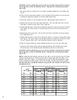
!NOTE:

  Measuring the hydraulic pressure to the puller is not an accurate means for deter-

mining the pulling tensions.  Component age and oil temperature affect hydraulic motor 

efficiency and torque output.  The following chart shows the different approximate pulling 

tensions at different oil temperatures with a 30 inch (762 mm) diameter Condux capstan.  

Use this chart as a comparative reference only and do not consider it to be the actu-

al pulling tensions.

Load

(30" Capstan)

lbs.             kN

Oil Temperature

42° F          6° C

106° F       41° C

160° F       71° C

Pressure

psi             bar

Pressure

psi             bar

Pressure

psi             bar

150             0.67

750             51.7

480             33.1

500             34.5

200             0.89

800             55.2

580             40.0

550             37.9

300             1.33

975             67.2

800             55.2

725             50.0

400             1.78

1150           79.3

1000           68.9

925             63.8

500             2.22

1375           94.8

1200           82.7

1125           77.6

600             2.67

1550         106.9

1400           96.5

1325           91.4

700             3.11

1700         117.2

1600         110.3

1825         125.8

800             3.56

1900         131.0

1800         124.1

900             4.00

2050         141.3

Содержание CableGlider

Страница 1: ...CableGlider FO Cable Puller USER S GUIDE SAFETY MANUAL USER S GUIDE SAFETY MANUAL ...

Страница 2: ...re to follow these instructions could result in serious personal injury or death If you have questions on SAFETY OPERATIONS APPLICATIONS CALL 1 800 533 2077 ADVERTENCIA Favor de leer y comprender todas las instrucciones de operación y seguridad antes de usar la máquina Si Ud no comprende las instrucciones favor de consultarle a su jefe READ MANUAL FIRST WEAR HARD HAT WEAR SAFETY GLASSES WEAR SAFET...

Страница 3: ...onics 10 c Setting Up the Electronic Control Box 11 d Digital Chart Recorder Set Up 11 e Data Download Instructions 13 Finish Puller Setup 14 Final Inspection 14 Puller Operating Instructions 15 Tear Down Procedures 16 a Remove Hydraulic Power Supply 16 b Disconnect Electronics 16 c Remove Capstan from Puller 16 Puller Calibration 17 a Verify the Puller s Calibration Settings 17 b Hydraulic Pressu...

Страница 4: ...ble flow control valve for adjusting maximum pulling speed and a manually adjustable pressure relief valve for adjusting the maximum pressure supplied to the hydraulic motor Technical Specifications A HYDRAULICS Open center system Pressure 2000 2500 psi 137 172 bar Flow 6 10 gpm 22 7 37 9 lpm Relief valve setting 2250 psi 155 bar Reservoir capacity 12 gallons 45 5 l Filtration 10 micron nominal Hy...

Страница 5: ...ids under pressure can penetrate the skin and cause serious personal injury Observe the following precautions to avoid hydraulic hazards 1 Tighten all connections before applying pressure Relieve pressure when connecting or disconnecting hoses and when servicing the unit 2 Check for leaks with a piece of cardboard Do not use your hands 3 Do not exceed working pressure of hydraulic hoses 4 Visually...

Страница 6: ...assembly to power supply 20 foot Owner s manual Shipping crate 2 Fiber Optic Cable Puller Package 3 Part Number 08690055 All Items in Package 1 Plus Electronic load cell mounted on puller Electronic control box with digital chart recorder Electronic cord from control box to puller Electronic cord from control box to foot control valve assembly Power cord vehicle s power point to control box NOTE I...

Страница 7: ...C SYSTEMS The Fiber Optic Cable Puller s hydraulic system uses quick connect couplings Keep all connections clean to avoid contamination and possible system failure Follow these steps to connect the hydraulic components 1 Connect the hydraulic supply hoses to the foot control valve assembly Ensure the pressure hose from the power source goes to the inlet of the foot control valve labeled PRESSURE ...

Страница 8: ... cable with the capstan rotating the opposite direction reverse the quick connect couplings of the hydraulic hoses on the puller see previous section 1 The foot control valve assembly is fitted with an adjustable speed control stop The speed control stop relieves operator foot fatigue by limiting the downward travel of the foot pedal Do not force the pedal if it does not move Adjust the speed cont...

Страница 9: ...stem Detailed instructions for using the equipment follows these explanations 1 Electronic Control Box Panel Switches Figure 5 Power Turns control box ON or OFF Set Tension Limit Sets the limit where the control box will stop the puller Press and hold UP or DN button to set the desired value Tension Limit Control Determines if the puller will stop rotating when the preset tension limit is reached ...

Страница 10: ...er the threaded portion of the receptacles This prevents the cord from coming loose during operation This cord is necessary to measure the ten sions sensed by the load cell 2 Connect the male end of the 3 pin footswitch control cord to the female connector on the Electronic Control Box labeled FOOTSWITCH see Figure 8 Connect the female end of the control cord to the male receptacle located on the ...

Страница 11: ... all electrical equipment precautions NOTE Always disconnect the power cord when the electronic control box is not in use When the power cord is connected to the electronic control box it energizes portions of the control box If the power cord is left attached when the control box is not in use it will drain the power supply 1 Turn the power switch on the Electronic Control Box to the ON position ...

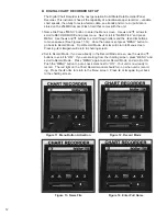
Страница 12: ...paces See Figures 11 14 Once the name is set press MENU button to go back to Record Mode From Record Mode or will return to Menu screen Pressing or again will return to charting screen 2 Set to Record Mode If you are already in the Record Mode screen use the and buttons to scroll to ON If you are starting from the charting screen press MENU and scroll to Record Mode Press MENU again to enter Recor...

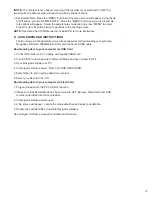
Страница 13: ...on software 256MB Flash Card card reader and USB cable Downloading data to your computer via USB Cord 1 Connect Recorder to PC or laptop with supplied USB cord 2 Turn ECB on and make sure that Record Mode has been turned to OFF 3 Open Navigator software on PC 4 In Navigator software select FILE and USE RECORDER 5 Select Open to pull in pulling data from recorder 6 Select your file and click OK Dow...

Страница 14: ...er of pull line on the capstan c Start the hydraulic power source Final Inspection WARNING Before placing the puller into operation always perform a final inspection of it and all components used a The foot control pedal has full range of motion and is in the neutral position b The electronic control box POWER switch is ON c The tension limit is set correctly d The TENSION LIMIT CONTROL is ON if o...

Страница 15: ... it or the pull line Follow these safety precau tions Do not wrap the pull line around a hand arm foot or leg Always be ready to release the pull line b When the TENSION LIMIT CONTROL is ON the puller will stop pulling if the cable tension exceeds the programmed limit of the electronic control box Release the foot pedal and the cable or pull line tension will slowly release Slowly reverse the pull...

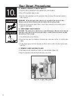
Страница 16: ...s to guard against contamination B DISCONNECT ELECTRONICS DANGER The electronic control box is an electrical device Electric shock hazards exist that could result in severe personal injury or death Follow all electrical safety precautions in this manual 1 Turn off the electronic control box 2 Disconnect the power cord between the electronic control box and the 12 Volt DC power supply 3 Unplug the ...

Страница 17: ...ontinue to pull until the relief valve opens The value shown on the dynamometer will be the force at which the pres sure relief valve is set for this hydraulic fluid temperature see next page 6 Release pressure to the puller 7 Set the electronic control box tension limit to the desired tension to be verified 8 Slowly apply pressure to the puller to tighten the pull line Continue to pull until the ...

Страница 18: ... until the desired maximum load is obtained 8 When the desired maximum load is obtained tighten the lock nut on the relief valve 9 Verify the relief valve setting by slowly applying pressure until the relief valve opens Check the value on the dynamometer and adjust the relief valve if necessary CAUTION Use the relief valve pressure only as a backup to the electronic tension control system or other...

Страница 19: ...ntrol system automatically calibrates itself to the 12 30 and 42 Condux capstans simply by turning the Capstan Selection Switch To verify calibration see section 11 A NOTE If the puller calibration is in question contact the factory for calibration information at 1 800 533 2077 ...

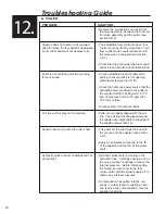
Страница 20: ...pull line must be placed around the capstan at a slight angle to the edge of the capstan see section 7 A The posts on the shaft must line up with the grooves on the capstan see section 5 D Apply an anti seize compound to the ID of the capstan and the OD of the puller shaft Hydraulic pressure is remaining in the hydraulic lines Carefully unscrew one of the quick connect couplings to relieve the int...

Страница 21: ...Press the Prog Button and button simultaneously Press the and buttons to increase or decrease the tension limit Press Prog to save the set point see section 6 C 3 Footswitch is not properly connected to the elec tronic control box Verify all connections are made and are tight see section 6 B 2 Capstan stops rotating before line tension reach es preset load limit programmed into electronic tension ...

Страница 22: ...rol if it works re assemble body spool upper knob steel and flow adjustment If foot control still sticks loosen capscrew without removing body spool lower move foot control up and down full stroke tighten cap screw and assemble body spool upper knob steel and knob flow adjustment D ROUTINE MAINTENANCE CLEANING SCHEDULE 1 After Every Pull Inspect all fasteners and locking pins to insure they are no...

Страница 23: ... 762 mm diameter 4 wide 102 mm 08675230 Capstan 30 inch 762 mm diameter 8 wide 203 mm 08675430 Capstan 42 inch 1 067mm diameter 08675436 Capstan 50 inch 1 270 mm diameter 08675220 Remote Mounting Stand 08675115 Pole Mounting Frame 08676000 Hitch Mount 08675908 Base Mount Weldment3 08675130 Side Mount Weldment3 08675138 Floor Socket Mount Cast3 02260801 See section 4 A for details on Package conten...

Страница 24: ...onal Incorporated warrants to the original purchaser for use that the goods or any component thereof manufactured by Condux International will be free from defects in workmanship for a period of one year from the date of purchase provided such goods are installed maintained and used in accordance with Condux s written instruc tions Components not manufactured by Condux International but used withi...

Страница 25: ...d in USA Literature Part Number 08675881 Revision Number 2 7 Condux International Inc P O Box 247 145 Kingswood Drive Mankato MN 56002 0247 USA 1 507 387 6576 1 800 533 2077 FAX 1 507 387 1442 Internet http www condux com E mail cndxinfo condux com ...

Отзывы: