


SERIES CHARGING CONTACTS MANUAL
12
WARNING
Before performing inspections and/or maintenance procedures, ensure all power is disconnected and all safety procedures are followed.
SECTION 3 - MAINTENANCE
System Inspections
1.
Perform the first inspection after the charging system has
cycled 100 times.
2.
Ensure that all electrical and mechanical connectors are
properly secured, and that the mechanical alignment is within
specification. Reference the provided drawing for additional
alignment detail.
3.
Perform periodic inspections every 15,000 – 20,000 charging
cycles. During these inspections ensure that all electrical and
mechanical connectors are properly secured.
Brushes
1.
Inspect the electrical brushes on the collector for wear. If
the brush is worn to the wear line etched into the side of the
brush, the brush is considered worn and should be replaced.
See
Figure 3-1.
2.
Inspect connection at the brush post to ensure they are still
torqued to 5.7 N-m(50 IN-LB) on the power brushes and 1.1
N-m (10 IN-LB) on the signal brushes.
3.
Inspect the contact surfaces on the base plate for wear.
4.
Remove surface dirt, oxidation, pitting, and other contaminants
from the contact surfaces via a brass brush or 320 grit sand
paper.
CAUTION
Do not use solvents or chemicals to clean the contact surfaces
and/or brushes.
Brush Springs
1.
Inspect and test the brush springs to ensure proper contact
pressure.
2.
Signal brush force for a single brush should measure between
.40-.55 lbf at minimum compressed distance for operation
(.5mm from free air state) and 2.00-2.45 lbf at maximum
compressed distance for operation (20.5mm). Power brush
force for a single brush should measure between 10.00-13.15
lbf at minimum compression distance for operation (.5mm from
free air state) and 18.00-22.50 lbf at maximum compressed
distance for operation (20.5mm). See
Figure 3-2
Electrical Connections
1. Inspect all electrical connections for corrosion.
2. Ensure that all fasteners are properly tightened.
NOTE
•
Poor electrical connections can lead to increased
electrical resistance and poor charging performance.
0.787 (20)
Minimum
Figure 3-1:
Brush Height Measurement
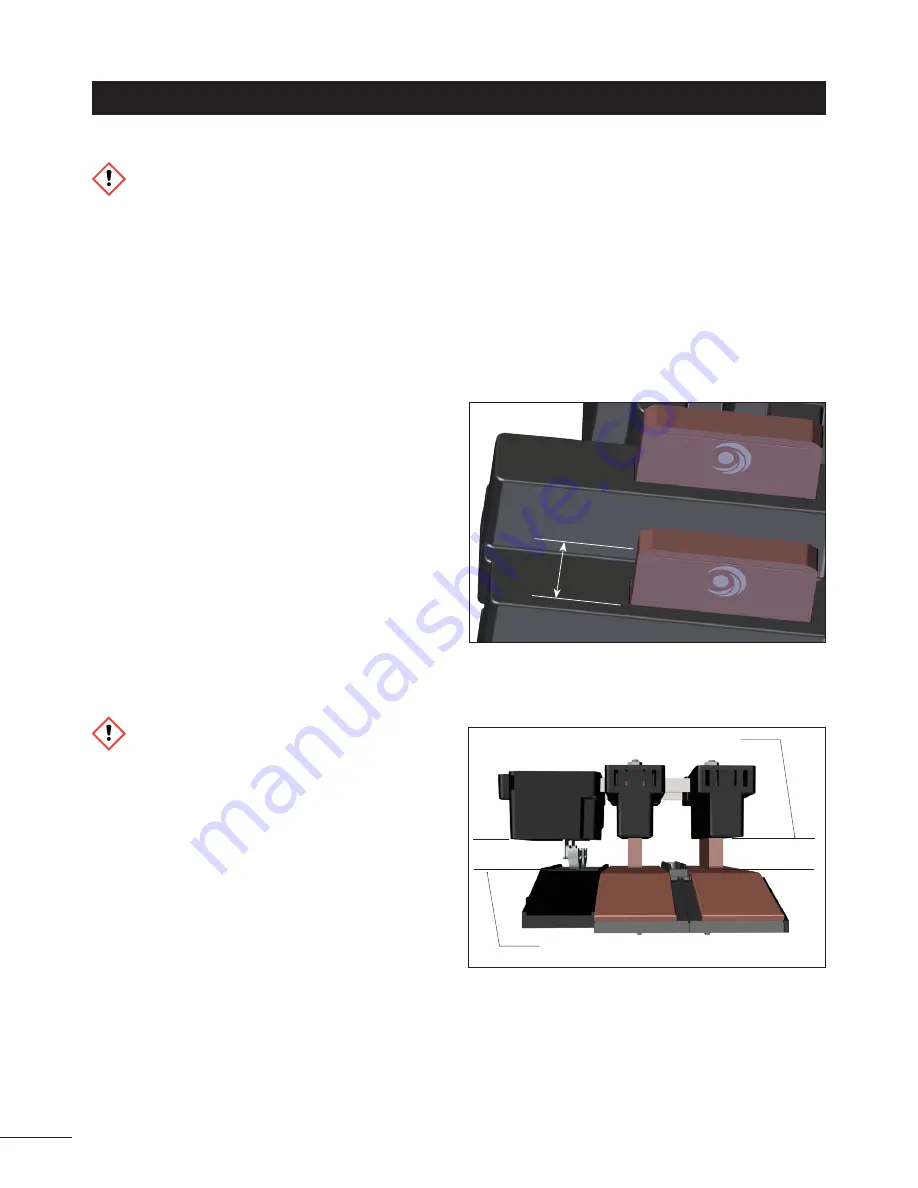
Figure 3-2:
Target Mounting Distance at Mid-Stroke
13.3 +/- 10 mm
11.6 +/- 10 mm
Signal contacts
Power contacts


