background image

Step 1: Please make marks based on bracket dimensions for
drilling the hole. Drill four 

φ

8 holes over 60 mm depth, and

drive the swell plastic buttons into the holes.

Step 2: Thread all cables through the cable hole on the side of the
bracket,as shown in the figure 3-2.

Step 3: Attach the high speed dome to the bracket, the tighten the
three screws, as shown in figure 3-3

Step 4: Mount the high speed dome to the wall or ceiling and
tighten the four screws on the bracket completely.

Figure 3.1 Bracket Dimensions

Figure 3.2 Aligning the screw holes

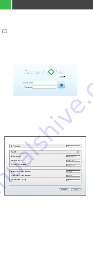
Figure 4.1 Log in

Figure 4.2 Local Network

Figure 4.3 Added a trusted site

Figure 4.4 Configuring ActiveX control and plug-in

Figure 4.6 Alarm

Figure 4.5 Live Video

Figure 3.3 Fixing the bracket and dome

3

INSTALLATION STEPS

4

QUICK CONFIGURATION (E.G IE)

5

APPENDIX: HAZARDOUS SUBSTANCE DECLARATION

INSTALLATION STEPS

Step 1: Open Internet Explorer, enter the IP address of IP camera (default 
value: 192.168.0.120) in the address box, and press Enter. The login page is 
displayed as shown in Figure 4.1.
Step 2: Input the usre name and password.

The default user name is admin. The default password is admin.
Change the password when you log in the system for first time to ensure
system security. You can change the system display language on the 
login page.

Note: Some firmware versions may have enhanced security enabled. If 
so, you will be prompted to create a new unique User Name and 
Password upon initial log-in.

Step 3: Click Login, the main page is displayed.

4.2 Modify IP address
Choose Configuration > Device > Local Network, the Local Network 
page is displayed.

Enter the IP address in the IP Address box and click Apply as shown
in figure 4-2.

After successfully modifying the IP address, please use the new IP 
address to log in the web interface.

Step 3: Download and install the player control as prompted.

Connection:
Step 1: Connect microphone to audio input interface of camera.
Step 2: Connect speaker to the PC audio output interface.
Step 3:  Log in to camera Web, click       to turn on.

4.4.2 PC          Camera
Step 1: Connect microphone to PC audio input interface.
Step 2: Connect speaker to camera audio out interface.
Step 3: Log in to camera Web, click       to turn on two-way audio.

This section does not apply to camera models that do not support alarms.

Alarm input and Alarm output connection:
Step 1: Connect alarm input device to Alarm IN0 and Alarm COM0
of multi-head cable.
Step 2: Connect alarm output device to Alarm OUT1 and Alarm COM1 of 
multi-head cable, alarm output interface can connect to normal open 
device only.
Step 3: Log in to Web, Choose Configuration>Alarm>I/O Alarm, set the 
parameters as shown in figure 4-6.
Step 4: Choose Configuration>Alarm>I/O Alarm Linkage, enable the I/O 
Alarm and set the parameters of Schedule Setting.

If the repair tips displayed when installing the control , please 
ignore the prompt, and continue the installation, the login page 
is displayed when the control is loaded.

To browse a real-time video, click Live Video. The Live Video 
page is displayed, as shown in figure 4-5.

This section does not apply to camera models that do not 
support two-way audio.

4.3 Browsing Video
To ensure the real-time video can be played properly, you must 
perform the following operation when you To ensure the real-time 
video can be played properly, you must perform the following 
operation log-in to the web browserfor the first time.

4.1 LOGIN

78.3

100

4- Ø6.5

63

63

4- Ø6.2

Ø115.5


NOTES

NOTES

NOTES

NOTES

L ocal Networ k 


Step 1: Open Internet Explorer. Choose Tools > Internet options > 
Security > Trusted sites > Sites, in the display dialog box, click Add, as 
shown in figure 4-3.

Step 2: In Internet Explorer, choose Tool > Internet Options > Security > 
Customer level, and set Download unsigned ActiveX control and 
initialize and script ActiveX controls not marked as safe for scripting 
under ActiveX controls and plug-ins to Enable, as shown in figure 4-4.

4.4 Two-Way Audio

4.4.1 Camera          PC

4.5 Alarm Configuration


P

O

O

O

O

O

P

P

P

P

P

P

P

P

P

P

P

P

P

P

P

P

P

P

P

P

Содержание VHSDIR-680EXT-IP

Страница 1: ...Quick Setup Guide IP HIGH SPEED DOME VHSDIR 680EXT IP VHSDIR 970EXTL IP VHSDIR 930EXT IP3M ...

Страница 2: ...lling the device The manufacturer shall not be held responsible for device damage caused by users non conformance to these requirements Strictly conform to local electrical safety standards and use power adapters that are marked with the LPS standard when installing and using this device Otherwise this device may be damaged Use accessories delivered with this device The voltage must meet input vol...

Страница 3: ... dry cloth For stubborn dirt dip the cloth into slightly neutral cleanser gently wipe the dirt with the cloth and then dry the device Do not jam the ventilation opening Follow the installation instructions provided in this document when installing the device Keep the device away from heat sources such as radiators electric heaters or other heat equipment Keep the device away from moist dusty extre...

Страница 4: ...oftware and hardware described in this manual Updated information may be added to new versions of this manual without prior notice This manual may contain misprints inaccurate technical information or product function and operation descriptions that are slightly inconsistent with the actual product This manual is only for reference and does not ensure that the information is totally consistent wit...

Страница 5: ...em for t 1 1 is consistent Table 1 1 Packing list Component Quantity Remark High Speed Dome Camera Quick Setup Guide USB No 4 Hex Wrench Slotted Screwdriver Terminal Block A Pair of gloves Power Adapter Wall Mount Bracket Bracket Connector Stainless hexagon screw M5 x 12mm 1 1 1 1 1 2 1 1 1 2 4 Optional Optional ...

Страница 6: ... p u t A u d i o O u t p u t 4 3 2 8 7 6 5 1 Table 2 1 Multi head cable description Brown Alarm output channel 1 Alarm input channel 3 Alarm input channel 4 Alarm input channel 5 Alarm input channel 2 Alarm input channel 1 Alarm output channel 2 Alarm output channel 1 common terminal Alarm output channel 1 common terminal R ed Black Brown Black R ed 1 ID Core Orange Yellow Black Orange Black Yello...

Страница 7: ...nput Red core Black core AC 24V power supply B NC Video 6 7 8 Grounding wire Yellow Green RS485 RS485 N A N A Sends an analog video signal You can connect the camera to a TV monitor through this port to view the analog video Connects to a standard Ethernet cable Connects to an externalaudio device such as a speaker Receives an analog audio signal from devices such as a microphone Supply power for ...

Страница 8: ...Figure 2 2 Dimensions Unit mm Different products may have different multi head cabbles please refer to the actual product 2 2 Product Dimensions NOTES ø9 Ø205 332 172 75 ...

Страница 9: ...he bracket as shown in the figure 3 2 Step 3 Attach the high speed dome to the bracket the tighten the three screws as shown in figure 3 3 Step 4 Mount the high speed dome to the wall or ceiling and tighten the four screws on the bracket completely Figure 3 1 Bracket Dimensions Figure 3 2 Aligning the screw holes Figure 3 3 Fixing the bracket and dome 3 INSTALLATION STEPS INSTALLATION STEPS 78 3 1...

Страница 10: ...Device Local Network the Local Network page is displayed Enter the IP address in the IP Address box and click Apply as shown in figure 4 2 After successfully modifying the IP address please use the new IP address to log in the web interface 4 3 Browsing Video To ensure the real time video can be played properly you must perform the following operation when you To ensure the real time video can be ...

Страница 11: ...e repair tips displayed when installing the control please ignore the prompt and continue the installation the login page is displayed when the control is loaded To browse a real time video click Live Video The Live Video page is displayed as shown in figure 4 5 This section does not apply to camera models that do not support two way audio NOTES NOTES 4 4 Two Way Audio ...

Страница 12: ...not apply to camera models that do not support alarms Alarm input and Alarm output connection Step 1 Connect alarm input device to Alarm IN0 and Alarm COM0 of multi head cable Step 2 Connect alarm output device to Alarm OUT1 and Alarm COM1 of multi head cable alarm output interface can connect to normal open device only Step 3 Log in to Web Choose Configuration Alarm I O Alarm set the parameters a...

Отзывы: