


DeviceMaster Primo Hardware Installation
7
Connecting a Previously Configured Primo
9.
Install a device driver on your PC host if you want to use the serial port as a
COM or tty port. See
and
on Page 1 to continue the installation.
To use pair-connect or raw-connect (socket mode), see
Dev_Mstr/Primo/Raw_Pair/raw_pair.pdf
Connecting a Previously Configured Primo
Use the following procedures to connect a previously configured DeviceMaster
Primo; that is, the IP has been configured for your network.
1.
Connect the appropriate serial cable between the Primo and the serial device.
See
The Serial Connector and Building Cables
on Page 8, if you need to build a
cable.
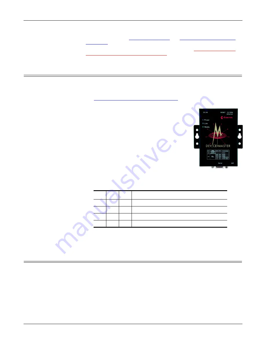
2.
Plug the power adapter DC plug into the jack
labeled
DC-IN
.
3.
Plug the power adapter into an electrical outlet.
Note:
There is no on/off switch. The Primo
automatically turns on when plugged into the
outlet. The
PWR
LED on the Primo top panel
will glow to indicate that it is receiving
power.
4.
Connect a straight-through Ethernet cable between
the 10/100 Base-T jack and the network hub.
Note:
The
Link
LED will light when the Primo is
properly connected to a live Ethernet device
or network. Orange indicates a 10 Mbps
Ethernet connection and green indicates a 100 Mbps Ethernet
connection.
5.
Set the DIP switch, using the following table to set the interface mode:
Note:
After changing the setting of
SW1
, you must wait a few seconds for the
green
Ready
LED to turn off and on, indicating that the function of the
serial port has been changed.
Replacing Hardware
Follow this procedure, to replace a DeviceMaster Primo with another
DeviceMaster Primo in an existing configuration.
1.
Disconnect the power from the Primo to be removed from service.
2.
Remove the old unit and attach a new or spare Primo.
3.
Connect the new Primo to the network hub or server NIC.
4.
Connect the power source to the new Primo.
5.
If necessary, change the driver to reflect the MAC or IP address of the new
Primo.
SW1 SW2 SW3
Interface Mode
OFF OFF OFF RS-232 Data Comm
OFF ON
RS-422
ON
OFF RS-485 by RTS (Ready to Send)
ON
ON
RS-485 by ADDC (Automatic Data Detection


