Optimizing Satellite Communications
www.comtechefdata.com
SMS-301 Modem Protection Switch
SPECIFICATIONS
System
Data Interface
EIA-232, V.35, EIA-422, G.703, and MIL-STD-188-114
Data Rate
20 Mbps max.
IF Interface impedance
75
Ω
BNC (50
Ω
optional)
IF Frequency
50 to 180 MHz
Operation Modes
Auto/manual, local/remote
Power
90 to 264 VAC, 47 to 63 Hz, 30W max.
Size
19 inch W x 15.2 inch D x 1.75 inch H (1RU) (48.2 x 38.6 x 4.4 cm)
Weight
9 lbs. (4.0 kg) max.
Controls
Switch Remote/local
Modulator
A/B online select or auto
Demodulator
A/B online select or auto
Indicators
Power Supplies
1, 2 on
Mode
Automatic or manual
Modulator A/B
online
Demodulator A/B
online
Faults
Transmit, receive, system, and stored
M&C
Remote Monitor and Control
9-pin D sub connector, EIA-232 or EIA-485 (2- or 4-wire), front panel selectable
Monitor and Control
Serial Interface
EIA-232 or EIA-485, programmable
Baud Rate
150 to 19200 bit/s, programmable
Parameters Controlled
Start/stop, parity, data bits
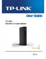
SMS-301 BLOCK DIAGRAM
SWITCH M&C
LOGIC
MODEM A
MODEM B
TRANSMIT IF
TRANSMIT IF
RECEIVE IF
RECEIVE IF
BASEBAND DATA
TX/RX
BASEBAND DATA
TX/RX
MODEM REMOTE
EIA-485
J13
J14
STATUS/FAULTS
REMOTE
CONTROL
J3
J6
J7
J10
J4
J8
J1
J9
J5
J2
SPLITTER
BASEBAND DATA I/O
TO/FROM CUSTOMER
RECEIVE IF
50 TO 180 MHZ
FROM
DOWN CONVERTER
TRANSMIT IF
50 TO 180 MHZ
TO UP CONVERTER
EIA-232 OR EIA-485
HOST TERMINAL
OR COMPUTER
1 : 1 SWITCH