QAM Marker
Signal Source
rev1.0.5 August 15, 2017
18
Section 3 - Calculate the Required QAM Marker Power Level
The total marker power is set to a level 30 dB less (± 0.5 dB) than the calculated total QAM power level.
Example: Total QAM Power Level calculated: 35.82 dBmV. Subtract 30 dB and set the marker power to
this level. 35.82 dBmV - 30 dB = 5.82 dBmV (± 0.5 dB)
Section 4 - Measuring the QAM Marker Power
1)
The QAM Marker Signal is comprised of a 1283 Hz, 1511 Hz, or 1663 Hz signal in a double sideband,
suppressed carrier, modulation scheme.
2)
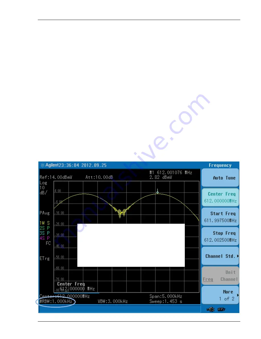
Set the spectrum analyzer to a 5 kHz span centered at the marker frequency. For best results, use a
RBW setting between 1 kHz and 30 Hz with 100Hz or 30Hz providing the best results. If the spectrum
analyzer does not have a RBW small enough to resolve the two sidebands, you will see a single
‘haystack’ type trace. In this case, all of the marker power is indicated by the single trace and the 3
dB correction factor is not applied. Disable the trace averaging mode.
3)
As illustrated in Figure 2, the two marker sidebands and perhaps some leakage of the suppressed
carrier at the center frequency will be visible on the spectrum. Use the peak search function to
measure the power level of one of the sidebands, they both should be equal, and add 3 dB to this
value for the total marker power.
In this example: 2.82 dBmV + 3 dB = 5.82 dBmV.
In the event
a single sideband
of the QAM
Marker is used to measure the marker power
level, subtract an
extra 3 dB
(in the calculation)
to account
for the other sideband’s power. In
this example, the total marker power would be
2.82 dBmV + 3 dB = 5.82 dBmV (± 0.5 dB)

