background image


OMM Series 


User Manual 


Document No.: UM-OPM-2  Rev. A 
File Name:OPM-2 Optical Power Meter User Guide Draft


Confidential


4


8.


Reference Key 

a.


Short press momentarily displays the current reference value  

b.


Long press (> 2 seconds) sets current Power Meter measurement as the reference level.  
Two beeps will sound when the reference level has been set and will display dB units. 
When the reference value is set, it is only applied to the current wavelength.  Individual 
reference values for each wavelength can be set and stored separately.  After a reference 
value has been set and each time the wavelength is selected on the power meter, the 
measurement will use the correct reference offset automatically. The offset is shown in 
dB.  To get the absolute power measurement, press the dBm/dB/mW key until the 
measurement in dBm is shown. 
Note: Deleting all of the stored values will not delete the reference measurements. 

9.


Power key 

a.


Short press until beep sounds to power on with auto-off function Active 

b.


Long press (>2 Seconds after beep) when powering on Disables auto-off function 

c.


Meter will display “auto-off” when function is enabled. 


10.


Unit of Measure selector key 

a.


Press to cycle between dBm, dB and mW.  dBm units will always display the absolute 
measurement value.  dB units will show the delta between the absolute measured value 
and the stored reference level.  For example:  The measured power value is 5 dBm.  The 
Reference value has been set to 4 dBm.  The delta between the measured value and the 
reference level will be 1dB. 

b.


In “Load” mode, this key will function as the up arrow key to numerically cycle through 
stored measurements:  1, 2, 3 … 

11.


Backlight key 

a.


Press to cycle display backlight on and off 

b.


In “Load” mode, this key will function as the down arrow key to numerically cycle 
through stored measurements:  3, 2, 1 … 


1.3.4


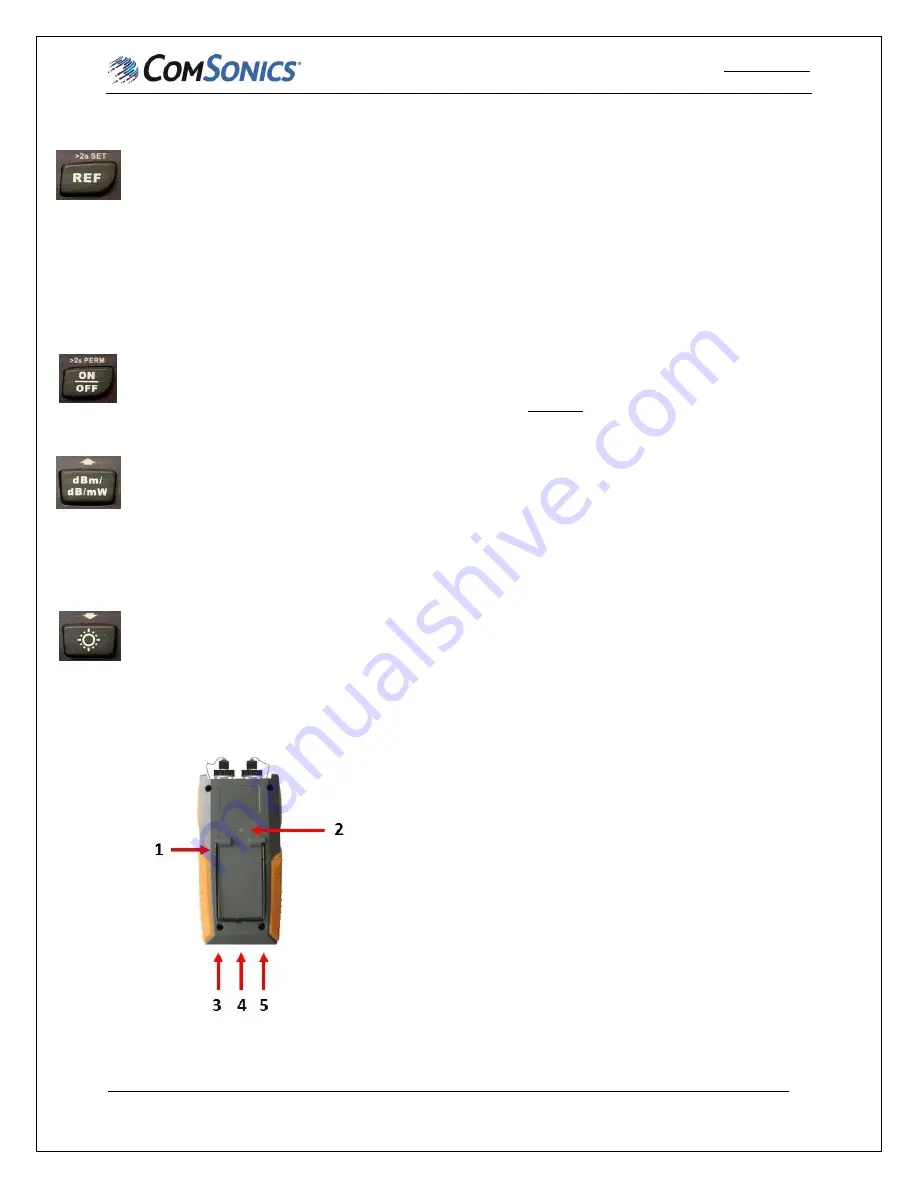
Bottom and Back Panel (Refer to Figure 1-4) 


1.


Kickstand 

2.


Battery compartment cover with locking mechanism 

3.


DC Power jack 

4.


Charging LED 

a.


Flashing red indicates charging 

b.


Green indicates full charge 

5.


USB Port 


Figure 1-4 


Содержание FHM2A01

Страница 1: ...User Manual Optical Multimeter O OM MM M 2 2A A1 1 O OM MM M 2 2B B1 1 O OM MM M 2 2A A2 2 a an nd d O OM MM M 2 2B B2 2 R RE EV V A A J Ju ul ly y 2 20 01 18 8...

Страница 2: ...resentation or warranty that using any products in the manner described herein will not infringe any patents of third parties The exclusion of implied warranties may not apply in all cases under some...

Страница 3: ...symbol calls your attention to information that if ignored can adversely affect the performance of your ComSonics product or that can make a procedure needlessly difficult LASER DANGER The Laser symbo...

Страница 4: ...AND FUNCTION OF COMPONENTS 1 1 1 INVENTORY 1 1 2 FEATURES 1 1 3 DESCRIPTION 1 CHAPTER 2 OPERATION 5 2 1 PERFORM OPTICAL POWER TEST 5 2 2 TWIN MODE 5 2 3 PERFORMING A FIBER LOSS TEST 6 CHAPTER 3 PC CON...

Страница 5: ...1 2 Features A High performance Optical Power Meter B Interchangeable connectors C Measures six different wavelengths D Laser light source output on two or three wavelengths E Auto off function saves...

Страница 6: ...nt reference setting 3 Modulation Indicator Displays modulated CW signal If none of the tones are shown on the display then they are all off 4 TWIN mode indicator a Single Auto wavelength detection of...

Страница 7: ...ta files at once press and hold for 2 seconds The meter must be in the load mode where the stored measurements are shown for this function to work 4 Load key a Short press to enter Load mode Displays...

Страница 8: ...hort press until beep sounds to power on with auto off function Active b Long press 2 Seconds after beep when powering on Disables auto off function c Meter will display auto off when function is enab...

Страница 9: ...at bottom center of display 8 Turn off the meter 9 Disconnect the tested fiber clean connections and reconnect to fiber network 2 2 TWIN Mode When the ComSonics OLS in the multimeter is paired with a...

Страница 10: ...B This provides a Reference level that will allow the power meter to measure signal level differences when measuring fiber loss 2 Repeat these steps for all wavelengths to be tested while ensuring the...

Страница 11: ...r NOTE The first time an OMM series meter is connected a USB driver will be installed 3 A USB logo will be displayed on the meter LCD 4 If desired the company name user name and notes may be entered i...

Страница 12: ...geable batteries and an AC charging adapter are supplied with the meter The rechargeable batteries may be replaced with standard 1 5 VDC AA batteries To replace the batteries 1 Use a common screwdrive...

Страница 13: ...0dBm Measuring Range 70 to 10dBm 50 to 26dBm 70 to 10dBm 50 to 26dBm Laser Source Parameters Output Wavelength 1310 1550nm 1310 1490 1550nm Connector fixed FC PC interchangeable FC SC ST customized Mo...

Отзывы: