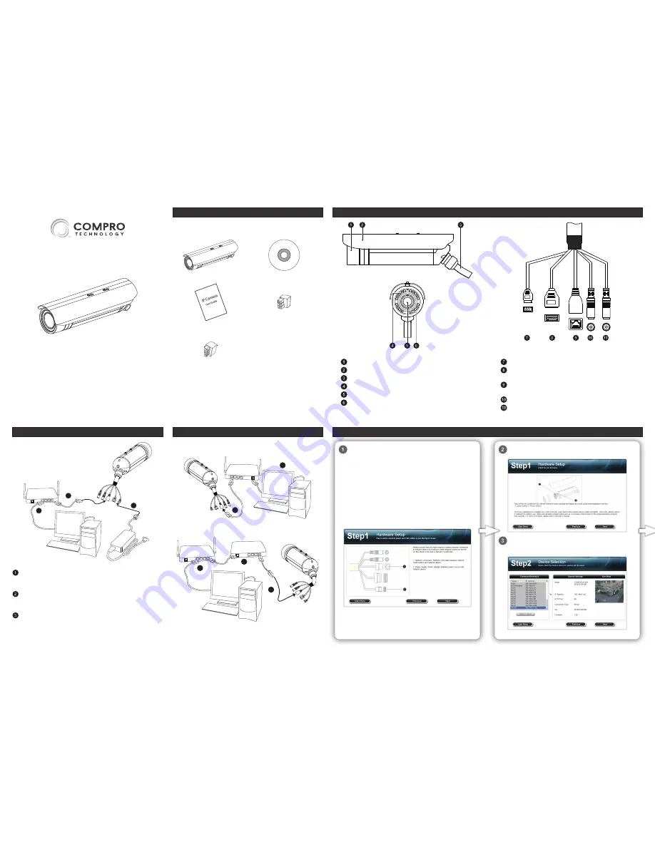
To install the IP camera’s software to your system, insert the
installation CD supplied with the IP camera into your CD-ROM
drive, and the iWizard installer will start automatically and guide
you through the installation process of the camera’s hardware
and software.
First you will be asked to select the displayed language of the
iWizard. Choose your language from the drop-down menu and
click [Next]. Then choose [Device Setup], and click on the type
of Compro surveillance product you wish to install, and select a
model from the list.
In this first step, connect the terminal cables according to the
illustration. And click [Next].
For NC450 users, adjust the varifocal lens. Then click [Next] to
search for your camera on the LAN network.
The wizard searches for all the available devices on your LAN
network. Select your camera from the list, and click [Next].
(Choose [Unblock] if you see Windows Security Alert dialog box.)
Please check the package contents on your hand. If anything is
missing, please don’t hesitate to contact your local distributor.
Network camera
Installation CD
Quick start guide
3-pin power terminal block x 1
7-pin I/O+RS485 terminal block x 1
Power connector:
A 3-pin power connector.
IO & RS-485 connector:
Connect to all sorts of I/O devices
or Pant/Tilt mount controlled via RS-485 port.
Ethernet connector:
Connect to the Ethernet port of your
network hub/switch.
Audio out (green):
Connect to an external speaker.
Microphone in (pink):
Connect to an external microphone.
Connecting the Cables
1
2
3
LAN cable from PC to hub/router:
If your LAN cable from PC has
been connected to the cable/ADSL modem, please re-connect it to
the Ethernet port of your hub/router.
Ethernet port on the camera side:
Use a RJ-45 LAN cable to connect
the Ethernet port of the IP camera to the Ethernet port of your hub/
router.
Power adaptor (optional accessory):
Attach the power adaptor
to the camera’s power connector and connect the power plug to a
power outlet.
The following are the cabling scenarios for your IP camera to take
advantage of its Power-over-Ethernet feature.
1
2
PoE Switch
(802.3af class3)
Connecting to a PoE-capable LAN switch
1
2
3
Switch
MidSpan
Connecting to a LAN switch through a midspan
Initial Software Setup
Lens cover
Sunshield
All-in-one terminal cable (power, IO, Ethernet, and audio )
IR LEDs
Lens
Light sensor (appearing green)
NC420 / NC450
Hardware Overview
Package Contents
Side View
All-in-One Terminal Cable
Front View
PoE Setup
Network Camera
Quick Installation Guide


