background image

Paging Interface Adapter 

26 


MASTER – SLAVE PROGRAMMING 

As stated earlier in this manual, all contact input programming is accomplished on the Master unit. Here  
is an example of a typical multiple host input location.  The user has 3 host systems on different floors,  
each unit has different outputs. Floor 1 – Master unit, 64 inputs, Floor 2 – S1, 16 inputs and Floor 3 – 
S2, 20 inputs. 
 

System Configuration 


1. Program Master as MASTER and select the amount of Slave units attached. 
2. Program S1 as S1 and S2 as S2. If attached to a host system that has pulsing, 
    be sure to select the host type on the slave unit as well as the master.  Select 64  
    contacts on the Slave. (Do Not Program any contacts on the slave). 
3. This Completes the Slave programming. 
3. On the master contact input screen program as follows.  

Example 


a. Contacts 1-64 – Information about inputs connected to the Master Unit. 


b. Contacts 65-80 – Information about inputs connected to Slave1. 


c. Contacts 129-148 – Information about inputs connected to Slave2. 

 
Each PIA3264 has the capacity of 64 input, with a maximum of 576 when all 8 slaves are connected. 
The contact number runs in sequence. Master 1-64. Slave1 65-128, Slave2 129 – 192, Slave3 193-256 
and so on till you reach the maximum. If the Slave only or master has less than the 64 inputs connected 
you only program the ones that are connected.  The contacts can be connected in any order. Ie. 1-16 or 
32-48. Just remember, only program those contacts that are connected. 
4. Connect the Master and first slave using an RJ45 crossover cable. 
5. Connect all Slaves together using an RJ45 patch cable. 
 

SEARCH and DISPLAY DATA 


Find Room 

1. Enter the room number you want to find in the field next to 

Room No.

2. Select 

Find Room.


3. All programming for that specific room will be displayed. 
 

Find Zone 

1. Enter the zone number you want to find in the field next to 

Find Zone


2. Select 

Find Zone.


3. All programming for that specific zone will be displayed


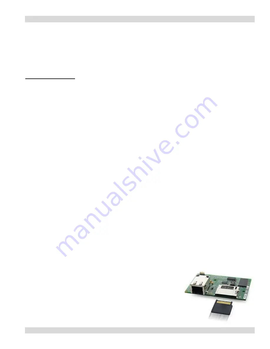
Removal of SD Card 

1. Remove power from the PIA3264. 
2. Remove the four screws holding the top cover on and set the cover  
    and screws aside. 
3. Locate the Main Processor board in the middle of the mother board. 
4. Push the card in 

GENTLY

 and the card will snap back. Now you      

    can remove it. 


Содержание PIA3264

Страница 1: ...Paging Interface Adapter Model PIA3264 Revision 2 3 4 ...

Страница 2: ... governing your use of the Software This agreement shall also be binding on any subsequent authorized licensee If you do not wish to agree to the terms of this Agreement promptly return the complete package to the distributor from whom you obtained this product You will receive a full refund provided you return the equipment in its original packaging If you have any questions concerning this Agree...

Страница 3: ...2 15 Programming Contacts for Elapse Time Report 16 Escalation and Repeat Settings 17 Development of Default Voltage Input File 16 18 Development of Default Non Voltage Input File 18 20 Maintenance 20 Reports 21 24 Edit zone room 25 Mixed inputs 25 Master Slave Programming Search 26 Micro SD Card 26 27 Installation 28 30 Master Slave connectively Troubleshooting 30 Specifications Terms Cable Pin O...

Страница 4: ...contact input that has been configured for no voltage Each contact can be configured for a different individual pager ID cap code Alert type A B C or D and repeats ranging from none 1 4 or until Change of State Time interval between repeats can be select from 1 minute to 59 minutes The paging protocol is a global setting of either Scope Motorola TAP v1 8 COMP2 and WaveWare In addition the PIA supp...

Страница 5: ...tion Always install to the outside Main Board 12 volt supply LED 3 volt supply LED 5 volt Supply LED Processor Board and 1GB Storage Card Input Terminal Strip Fuse Holder 1 32 inputs TB1 TB2 In Front Contact Logic Board Indicates Ethernet Connection Indicates 2 Green 1 Yellow SD Card Present ENSURE ALL POWER IS REMOVED BEFORE INSTALLING OR REMOVING THE CONTACT LOGIC BOARD AND OR MICRO SD STORAGE C...

Страница 6: ...heck with your network administrator before proceeding CHANGING PC IP ADDRESS 1 Locate and Change IP Address a Select Start Connect To Show all Connections 2 Right click on your Local Area Connection and select Properties 3 Right click Internet Protocol TCP IP and select Properties 4 Select Use the following IP address This will un select Obtain an IP address automatically 5 To the right of the IP...

Страница 7: ...tional 3 On the PC Internet Explorer Browser address line enter the Paging Interface Adapter IP address The IP address can be found on the main board 192 168 1 239 4 The following screen will appear 5 When configuring the operation of the PIA with a Host System select Configuration Settings 6 Enter the default User Name and Password Use id comppage Password pia3264 7 Click OK 8 The Global Setting ...

Страница 8: ... the next time you log onto the PIA3264 4 Save this information in a secure place If it is lost there is NO way to log onto the unit 5 The same procedure is used for changing the Log on and Password for the Reports 6 For the new password user id to take effect CYCLE THE POWER on the PIA Note You may use the same password for both Programming and Reports but may not use the the same Log On ID UserI...

Страница 9: ...ss You must log on to the PIA3264 to change the IP address 1 Connect the PIA to a stand alone PC using the supplied RJ45 Cross Over cable 2 Apply power to the PIA and turn on unit the GREEN power light will illuminate 3 On the PC Internet Explorer Browser address line enter the Paging Interface Adapter IP address 4 When the log on screen appears enter your log on information 5 The following screen...

Страница 10: ... string Ie 192 168 1 If Slave units are to be connected to the master via RS485 or connected to the Local Area Network you must assign new IP Addresses If connected to a LAN check with the network administrator for correct Sub Mask and Gateway numbers It may not be necessary to change these numbers On each Slave you must enter the Master s IP Address and the Slave s IP Address At the same time you...

Страница 11: ... the GREEN power light will illuminate 3 On the PC Internet Explorer Browser address line enter the Paging Interface Adapter IP address 192 168 1 239 4 When the log on screen appears enter your log on information 5 The following screen will appear 7 On the Global Setting page in the space next to the IP Address enter the new IP address you want the unit to have Be sure to record the new IP address...

Страница 12: ...ate If a host system selection is not required and you are using a momentary contact closure select Fast Trigger Input This will set the input contact closure time for detection to less than 75 mS This will accommodate both Voltage and Non Voltage input Not for use with pulsing inputs Unit ID Select the type of unit to be programmed Each unit must be identified as a Master or Slave 1 thru 8 1 Mast...

Страница 13: ...er with 64 inputs and 1 slave attached with 16 inputs On the Contact Programming screen you would program the first 64 contacts with the information of the inputs connected to the master The next 16 contacts 65 80 you would program for the information of the inputs connected to the Slave Monitoring Pagers This option has two global pager IDs that can be identified so all alarm notification will be...

Страница 14: ...o the processor memory Changes will not be effective unit you have saved them to the database Function Button Save Database Select to write programmed data to on board processor Contact Settings Displays the Contact Input zones to be programmed Program Authentication Settings Allow the user to change log on ID and Password for Contact Programming Report Authentication Settings Allow the user to ch...

Страница 15: ...be disregarded Contact Input Programming Each contact input can be programmed for individual messages for each state The user can select the type of input Voltage or Non Voltage and normal state of that contact Each contact can be programmed with different Pager IDs Repeat times and Escalations The PIA is shipped with 16 inputs standard upgradeable to a total of 64 in blocks of 4 The unit can be s...

Страница 16: ...lobal Setting Screen of the master On the Slave you would select S1 and 16 contacts on the Global Setting Screen When you program the Contact Screen information you enter the data for ALL the input on the master unit 1 64 and the information for the inputs on the S1 unit 65 80 Voltage Input Contact Programming Screen Start on Zone input 1 1 Select the Type of inputs see page 10 for definition a Vo...

Страница 17: ...al 2 min later 1st Repeat 2 min later 2nd Repeat 1st Escalation the time set 2 Esc The same for the 3rd Esc When zone is physically reset Original and Esc pagers will be notified RUR repeat until reset 5 0 Original and every 5 minutes till the point is reset Note Resets will not be transmitted or logged unit the zone is physically reset 8 Pager ID a If no pager number is required the blank must ha...

Страница 18: ... Prev or Next a In the box next to Fine Zone enter the number of the contact you want to edit b Select Fine Zone c The zone information for the zone you entered will appear You can now make changes 15 Select Next to display the next input to be programmed a Continue until all inputs have been programmed Non Voltage Input default If the unit was ordered for Non Voltage input you must have the Fuses...

Страница 19: ...type of pager IDs are used Scope 0100800 7 digits TAP 100 3 digits WaveWare 100 3 digits Comp2 100 3 digits c Select the Alerts type for each pager ID Alerts A D 8 Select the Repeat and Interval for each contact a Repeat 0 5 or RUR repeat until reset b When RUR repeat until reset is selected ESCALATION function is not available c Interval 2 5 10 15 20 30 Minutes 1 or 2 hours 9 Select Save to Zone ...

Страница 20: ... been programmed When all programming is complete select PRINT DATABASE Retain this copy and place a copy with the unit for any future questions or changes Function Buttons Page Two 1 PREV Go back to the previous input zone 2 NEXT Move to the next input zone 3 SAVE ZONE Save all data to memory 4 PRINT DATABASE Print a record of all information in current file 5 FIND ROOM Search feature displays da...

Страница 21: ...eport The database report is a complete record of all currently programmed zones on the Master and Slaves 1 Select Print Database from screen two 2 The system will display all the currently active zones 3 On the browser select File Print Select the printer you want the report to be printed Database Report Date 12 31 2008 Time 00 00 00 Zone 1 Active Bed Call Assistance Needed Room 222 Reset Bed Cal...

Страница 22: ... the data requested Below is a list of common search criteria 1 Room Number by Date This will show all call types for the given date and Room a Select Date and Select the date for the search b Select From Room and enter the Room number in the first blank and the Identifier if used leave the second blank empty c Select View Report 2 Room Number by Date and Type of Call This will show only the call ...

Страница 23: ...st blank c If no specific call type is desired select View Report 5 Room Number Date and Specific Shift All Call Types a Select Date and Select the date for the search b Select From Room and enter the Room Number in the first blank c Select Shift and then Select which shift d Select View Report Report by Room number The room number report is a list of all calls placed from a specific room on a spe...

Страница 24: ...Call Room 33 Reset 08 45 00 0301600 Bed Call Room 33 Elapse Time This report allows the user to create a report for a specific room day and calculate the elapse time for all calls for that room PIA3264 REPORT Report Date 12 24 2008 Report Time 14 20 09 Options Date Room Elapsed Time Type Log Date 12 23 2008 the date the report was taken from Room No 66 Log Time E Time Pager ID Message 12 44 32 030...

Страница 25: ...o edit d Select Find Room e The system will display the current data for that room f Edit the data and select SAVE ZONE Note After edit changes are saved select Print Database This will give you a complete list of all data on all zones MIXED INPUTS The PIA3264 has the ability to process different types of data on the same unit This option allows the user to select Non Voltage dry N O N C and Volta...

Страница 26: ...3264 has the capacity of 64 input with a maximum of 576 when all 8 slaves are connected The contact number runs in sequence Master 1 64 Slave1 65 128 Slave2 129 192 Slave3 193 256 and so on till you reach the maximum If the Slave only or master has less than the 64 inputs connected you only program the ones that are connected The contacts can be connected in any order Ie 1 16 or 32 48 Just remembe...

Страница 27: ...ista will recognize the card as a removal drive and assign it a letter 3 Create a directory and drag and drop the directories on the SD card into the directory you created Reinstalling SD Card into PIA3264 1 Remove SD Card from PC after all directories have been copied 2 Install SD Micro Card back into SD Adapter if removed previously 3 Insert SD Card adapter with Micro Card into holder on Main Pr...

Страница 28: ...top cover and sit aside 3 Using the hardware supplied mount the PIA3264 4 If the cable you are using has bundled wires strip the outside covering back 24 inches 5 Loop the cable in a U shape and attached by to the PIA3264 using the tie wraps provided Fig 1 6 Route the wire pairs through the access holes on the back of the unit 7 With the front of the unit facing you zones 1 32 are on the left and ...

Страница 29: ... board Attach the Point wire or Positive wire to terminal 1 Continue until all inputs are connected 9 Replace top cover and Phillips screws removed earlier 10 Connect the power lead to rear of the unit 11 Turn the power switch located on the front panel ON 12 The power light will illuminate 13 Connect the 9 pin to 9 pin serial Cable from the PIA3264 to the input of the Paging Encoder 14 Apply powe...

Страница 30: ... following sequence a Turn power on the Master b Turn the power on the slave units in order ie 1 2 3 5 The master Power LED will be ON 6 Each Slave s power LED will be ON and the yellow Data LED will flash on each slave as it reads the configuration from the master Once complete the LED will come on solid 7 In normal operation the slave s Yellow Data LED Green Power LED and will be ON solid Troubl...

Страница 31: ...eWare Programming Web Browser Connection RJ45 IP Address Default 192 168 1 239 MAC 00 90 C2 Additional six characters on processor board Approval FCC Title 47 Part 15 RoHS Compliant UL 1069 Ed 7 and CSA C22 2 205 Size 14 in x 10 5 in x 2 in Warranty Limited Life Time Patent US Patent Pending 61 291 719 Terms Fast Trigger Input Used with Dry Contact Input or Non Pulsing Voltage Input Closer Detecti...

Страница 32: ...l Voltage Input Slave1 Master Cross Cable RJ45 supplied Slave 2 Patch Cable RJ45 supplied Setup 1 All Programming is accomplished on the master 2 Master is connected to first Slave with the GREEN RJ45 Cross Over Cable 3 Each Slave is programmed to identify its slave number slave1 or 2 etc ...

Страница 33: ...C Reset 0 VDC Wiring Connection PRIOR TO CONNECTING POINT WIRES REMOVE JUMPER JP3 JP4 Point Wire to PIA pos 24Volts from Zone Board on 900 20X unit to PIA neg Card type CTBD4 Heritage MedCall Connection Type Voltage Alert High Activation 24VDC Reset 0VDC Wiring Connection PRIOR TO CONNECTING POINT WIRES REMOVE JUMPER JP3 JP4 Point wire 24VDC to PIA neg Gnd Neg to PIA pos Card Type CTBD4 Tektone Si...

Страница 34: ...ging Interface Adapter 34 Note JP 3 JP 4 is located on rear of the main board on the right and left of the board JP3 is for Ground on contacts 1 32 and JP4 is for 33 64 Main Board JP3 JP4 Cornell Diagram ...

Страница 35: ...Paging Interface Adapter 35 Cornell Continue ...

Страница 36: ...Paging Interface Adapter 36 Engineered Electronics ...

Страница 37: ...Paging Interface Adapter 37 Heritage MedCall ...

Страница 38: ...Paging Interface Adapter 38 ...

Отзывы: