


attach the phenolic servo arms to the outside of the metal
discs temporarily with a couple of drops of CA, making sure
that the servo arms are at exactly 90° to the bottom surface
of the stabs using a set square. Then remove the arms and
discs, drill through both, and secure with at least 2 small
bolts, washers and locknuts (M2 or equivalent size).
Make up the linkages from the hardware supplied, using
M3 threaded rods (90mm for inner servos, 65mm for outer
servos), with a quick-link and M3 nut at the servo-end, and
a ball-link in between the double horns secured with an M3
bolt and locknut. Add short pieces of Tygon fuel tube, or
similar, to make sure the quick-links cannot open in flight !
The last job is to fit the M3 stab retaining bolts and blind
nuts. Look inside the stabs and you will see the small ply-
wood reinforcement plates between the spar sleeve and
the bottom surface of the stab. Mark the bottom of both
stabs in the centre of this plywood. Install the aluminium
tube into 1 stab, and drill a 2.4mm hole right through the
stab surface, the plywood plate, sleeve and into the 20mm
aluminium tube. The centre of the hole should be about
34mm from the trailing edge of the stab. Thread the hole
with an M3 tap and secure it with an M3 x 16 bolt. To be
really secure, you can glue an M3 blind nut inside the stab
spar tube, as shown here, with some 30 minute epoxy and
micro-balloons. Wax or oil the bolt first!
Fit both stabs to the fuselage, check that they fit tightly to the fuselage at the roots, and then drill
the hole in the other stab and spar tube, thread as before, and secure with another bolt.
Counterbore the holes in the bottom surface of the stabs for the boltheads so that they fit flush
(see canopy frame section).
As mentioned earlier, the stabiliser incidence is adjustable, using a ball-wrench though the holes
in the bottom of the fuselage, but it has been pre-set at ‘neutral’ at the factory and should not
need adjusting.
Note:
Try to always leave the stab tube fixed in one stab, and never remove that one bolt, as it
is very difficult to find the right position for the stab tube again if it is removed from both stabs!
Rudder
Finished in 2 hours
Fit the rudder to the vertical stabiliser with the 4mm Ø brass
tube supplied, in the same way as the elevators. Check for
smooth movement. The dual phenolic rudder horns are
already glued in place at the factory during manufacture.
The rudder is a huge surface on the Extra 330L and the
choice of servo is up to you. For pattern flying 4 hi-torque
servos (eg: JR4421) would probably be sufficient, but if you
plan to fly 3D or radical freestyle we highly recommend
Composite-ARF SuperXtra 330L
(3.1m span)
20
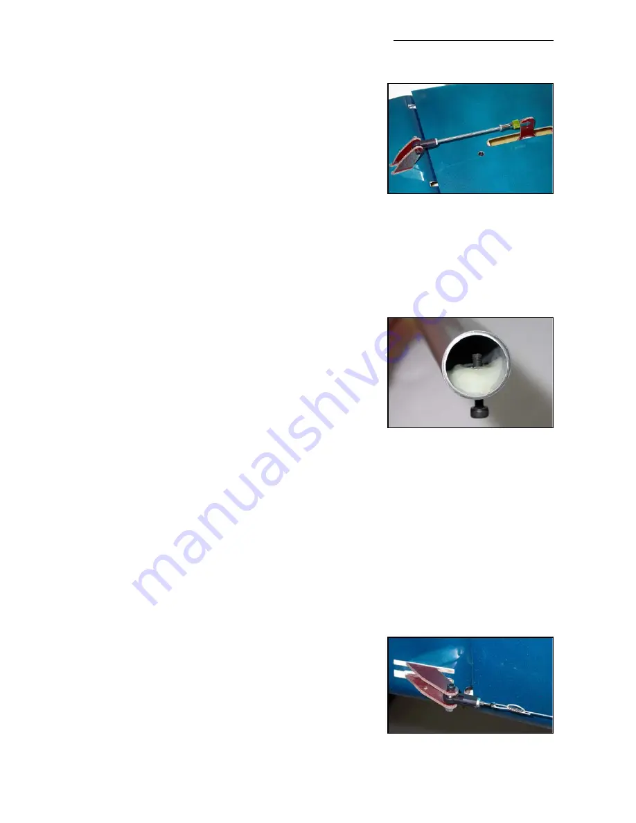
(above) The completed inner ele-
vator linkage. You can also see the
head of the M3 retaining bolt, with
the bolt head counterbored flush
into the surface of the stab.
(below) M3 blind nut glued inside
the stab spar tube with 30 minute
epoxy and micro-balloons mix.
(above) Pass rudder cable thru’
crimping tubes 2 times for safety.


