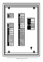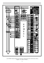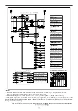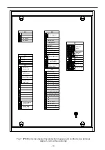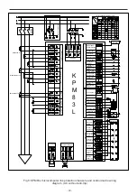
Fig 1 KPM83L Microcomputer
line
protection measurement and control device
terminal diagram (DC with anti-
trip
)
X1
01
02
04
03
Power 1 close position
Power 2 close position
Manual closing signal
DI4
D
I
3
Device maintenance in
Energy storage switch open
Reclose
locking/manual
tripping digital input
Spring without energy
storage
Grounding knife status
Signal reset
Remote location
01
02
04
03
08
07
06
05
13
14
15
16
11
12
10
09
Handcart test position
(upper knife)
Handcart test position
(lower knife)
13
14
15
16
11
12
10
Circuit
Reclose
out
10
12
11
16
15
14
13
X6
Signal power +
Protecting action
signal output
No power supply signal
output
Manual closing
05
Closer out
07
Power
01
Tripping out
37
Manual tripping
33
Protection tripping
31
Remote control allowed 11
01
02
03
17
18
19
20
18
17
Power supply -
02
Alarm signal output
DC 220V
+
DC 220V
-
X5
X3
X4
RS485B
RS485A
MASK
01
02
04
03
08
07
06
05
09
01
02
04
03
08
07
06
05
09
17
19
23
21
09
11
13
15
05
07
03
01
Uc
Ua
U0
IC
IA
Ic
Ib
Ia
Un
Ub
U0n
In
IB
Icn
Ibn
Ian
X7
I0
I0n
18
20
24
22
10
12
14
16
06
08
04
02
UX
UXn
Ground signal output
Protection trip signal
output
Control circuit
disconnection output
Reclosing action signal
output
Measurement
CT
current
Bus-bar
PT
voltage
Protection
CT
current
Zero sequence CT
current
Bus-bar
PT
no-volt
Circuit
PT
voltage
-13-
PT disconnection
signal output
Close position signal
Trip position signal
Self trip alarm
signal output


