Page 2
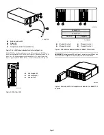
Figure 2. Dual ECB for dual-redundant controller configurations
Model 2200 controller enclosures use a different type of ECB that
does not require an ECB Y-cable (see Figure 3) and contain four ECB
bays. Two ECB bays support cache module A (A1 and A2) and two
bays support cache B (B1 and B2)—see this relationship in Figure 4.
Figure 3. ECB status LEDs
Figure 4. ECB and cache module locations in a Model 2200 enclosure
IMPORTANT:
When replacing an ECB (see Figure 5), match the vacant ECB bay with
the cache module it supports. This bay will always be next to the failed ECB.
Figure 5. Removing an ECB that supports cache module B in a Model 2200
enclosure
1
Battery disable switch
2
Status LED
3
ECB Y-cable
4
Faceplate and controls for second battery
1
ECB charged LED
2
ECB charging LED
3
ECB fault LED
CXO5713B
CACH
E
POW
ER
STATUS
SH
UT
OF
F
CA
CHE
PO
WER
STATUS
SH
UT
O
FF
3
~
4
2
1
CXO6358A
1
2
3
1
B1 supports cache B
2
B2 supports cache B
3
A2 supports cache A
4
A1 supports cache A
CXO6864A
4
2
1
3
Controller A
Controller B
Cache A
Cache B
CXO5608A
CXO6922B


