Compaq Prosignia Desktop 340 Series Скачать руководство пользователя страница 18

2–10

Compaq Prosignia Desktop 340 Series Computer

Spare Parts

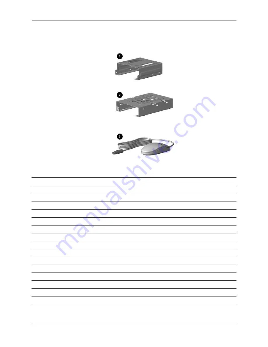
2.5 Miscellaneous Parts

Miscellaneous Parts

Item

Description

Spare Part

1

Diskette drive mounting bracket 

161734-001

2

Hard drive mounting bracket 

149807-001

3

Two-button mouse

166861-001

*

Option slot cover (5 ea)

304284-001

*

Creative Labs SBS52 speakers, Australia

125773-011

*

Creative Labs SBS52 speakers, Europe

125773-021

*

Creative Labs SBS52 speakers, Japan

125773-391

*

Creative Labs SBS52 speakers, U.K.

125773-031

*

Creative Labs SBS52 speakers, U.S.

125773-001

*

Altec ACS 233 speakers, Australia

135426-011

*

Altec ACS 233 speakers, Europe

135426-021

*

Altec ACS 233 speakers, Japan

135426-391

*

Altec ACS 233 speakers, U.K.

135426-031

*

Altec ACS 233 speakers, U.S.

135426-001

*Not shown

Содержание Prosignia Desktop 340 Series

Страница 1: ...er 2002 This document provides the reader with basic information for maintaining the computer It contains detailed instructions for the removal and replacement of all components spare part numbers for...

Страница 2: ...document is provided as is without warranty of any kind including but not limited to the implied warranties of merchantability and fitness for a particular purpose and is subject to change without not...

Страница 3: ...1 1 Generating Static 3 1 3 1 2 Preventing Electrostatic Damage to Equipment 3 2 3 1 3 Personal Grounding Methods and Equipment 3 2 3 1 4 Grounding Workstations 3 3 3 1 5 Recommended Materials and Equ...

Страница 4: ...11 4 6 Network Card 4 12 4 7 Fax Modem Card 4 13 4 8 Memory Module 4 14 4 9 RTC Battery 4 15 4 10Processor 4 16 4 11Front Bezel 4 17 4 12On Button Board 4 18 4 13System Board Bracket 4 19 4 14System B...

Страница 5: ...Compaq Prosignia Desktop 340 Series Computer 1 1 1 Product Description This chapter describes the model offerings and features of the Compaq Prosignia 340 Series Computer...

Страница 6: ...ith a mouse and keyboard A Compaq color monitor or other compatible monitor which is also required to operate the computer does not ship with the computer 1 2 1 Front Panel Controls and LEDs 1 Diskett...

Страница 7: ...tion 1 2 2 Rear Panel Connectors 1 Mouse 2 Keyboard 3 USB Ports 4 Serial Port 5 Parallel Port 5 2nd Serial Port 7 Audio Out 8 Game Port 9 Audio In Microphone Video AC Power Voltage Select Switch AGP C...

Страница 8: ...1 4 Compaq Prosignia Desktop 340 Series Computer Product Description 1 3 Serial Number Location The serial number is located at the rear of the computer below the power supply...

Страница 9: ...Compaq Prosignia Desktop 340 Series Computer 2 1 2 Spare Parts This chapter provides an illustrated parts breakdown and a listing of spare parts...

Страница 10: ...2 2 Compaq Prosignia Desktop 340 Series Computer Spare Parts 2 1 System Unit...

Страница 11: ...s Computer 2 3 Spare Parts System Unit Item Description Spare Part 1 Front Bezel with bezel blank and power button 149804 001 2 Hood sssembly 149800 001 3 Chassis not spared 4 System rear I O panel 14...

Страница 12: ...2 4 Compaq Prosignia Desktop 340 Series Computer Spare Parts 2 2 Mass Storage Devices...

Страница 13: ...e 5400 RPM 2 4 3 GB 161431 001 8 4 GB 168027 001 13 GB with mounting screws 161432 001 17 GB with mounting screws 168591 001 Optical drives 3 8 4 32C CD RW drive 294401 001 40X CD ROM drive 400807 001...

Страница 14: ...2 6 Compaq Prosignia Desktop 340 Series Computer Spare Parts 2 3 Cables...

Страница 15: ...drive cable 15 5 105875 001 N A this product Dual LED Power cable 387662 001 N A this product Dual device hard drive cable 1308950 005 N A this product Miscellaneous cable kit includes 298856 001 3 Op...

Страница 16: ...2 8 Compaq Prosignia Desktop 340 Series Computer Spare Parts 2 4 Standard and Optional Boards...

Страница 17: ...001 550 MHz Pentium III 176221 001 600 MHz Pentium III 176222 001 Memory module 3 32 MB 166890 001 64 MB 179190 001 128 MB 166966 001 Modems 4 56K V 90 International PCI modem 166358 002 56K PCI cont...

Страница 18: ...over 5 ea 304284 001 Creative Labs SBS52 speakers Australia 125773 011 Creative Labs SBS52 speakers Europe 125773 021 Creative Labs SBS52 speakers Japan 125773 391 Creative Labs SBS52 speakers U K 125...

Страница 19: ...national 135510 B31 Spanish 135510 071 Swedish 135510 106 Swiss 135510 111 U K 135510 031 U S 135510 001 Spacesaver keyboard Japanese 269513 291 Monitors not illustrated Size Description Spare Part 24...

Страница 20: ...2 12 Compaq Prosignia Desktop 340 Series Computer Spare Parts...

Страница 21: ...he device may function normally for a while then degrade in the internal layers reducing its life expectancy Networks built into many integrated circuits provide some protection but in many cases the...

Страница 22: ...n touching a sensitive component or assembly Avoid contact with pins leads or circuitry Place reusable electrostatic sensitive parts from assemblies in protective packaging or conductive foam 3 1 3 Pe...

Страница 23: ...res must directly contact dissipative surfaces Keep work area free of nonconductive materials such as ordinary plastic assembly aids and Styrofoam Use conductive field service tools such as cutters sc...

Страница 24: ...es described below To remove light stains or dirt use plain water with a clean lint free cloth or swab For stronger stains use a mild dishwashing liquid diluted with water Rinse well by wiping it with...

Страница 25: ...e parts to air dry before reassembly 3 2 4 Cleaning the Monitor Wipe the monitor screen with a clean cloth moistened with water or with a towlette designed for cleaning monitors Do not use sprays or a...

Страница 26: ...ensure that cables are placed in their proper location during the reassembly process Improper cable placement can damage the computer 3 3 4 Hard Drives Handle hard drives as delicate precision compon...

Страница 27: ...disc from the computer 2 Unlock the computer Smart Cover Lock using Computer Setup Turn off the computer and any peripheral devices that are connected to it CAUTION Turn off the computer before discon...

Страница 28: ...4 2 Hood 1 Prepare the computer for disassembly 2 Unscrew the thumbscrews at the back of the computer The screws will remain attached to the hood 3 Grasp the bottom of the hood and pull back slightly...

Страница 29: ...onnect all cables connected to the power supply cables to the hard drive CD drive diskette drive and system board 3 Remove the four screws that secure the power supply to the rear of the chassis 4 Sli...

Страница 30: ...4 4 Compaq Prosignia Desktop 340 Series Computer Removal and Replacement Procedures 4 4 Mass Storage Devices Item Description 1 Optical drive 2 Diskette drive 3 Hard drive...

Страница 31: ...rocedures 4 4 1 CD Optical Drive If a compact disc is jammed in the drive insert a straightened paper clip into the manual eject hole and push firm1y 1 Perform the preparation procedures 2 Remove the...

Страница 32: ...sktop 340 Series Computer Removal and Replacement Procedures 4 Remove the four screws from the side of the CD drive 5 Pull the CD drive straight out of the front of the chassis To replace the CD drive...

Страница 33: ...ries Computer 4 7 Removal and Replacement Procedures 4 4 2 Diskette Drive 1 Perform the preparation procedures 2 Remove the hood 3 Remove the power supply Section 4 3 Disconnect the power 1and data 2...

Страница 34: ...rew that holds the diskette drive and bracket to the chassis 5 Grasp the drive bracket assembly on both sides and pull it towards the rear of the chassis 6 Remove the four screws from the sides of the...

Страница 35: ...Perform the preparation procedures 2 Remove the hood 3 Disconnect the power 1 and signal 2 cables from the hard drive 4 Remove the screw holding the hard drive and bracket to the chassis 5 Carefully p...

Страница 36: ...Prosignia Desktop 340 Series Computer Removal and Replacement Procedures 6 Remove the four screws at the bottom of the hard drive bracket to release the hard drive To replace the hard drive reverse th...

Страница 37: ...val and Replacement Procedures 4 5 Video Card 1 Perform the preparation procedures 2 Remove the hood 3 Remove the screw holding the video card bracket to the chassis and pull the video card out of the...

Страница 38: ...and Replacement Procedures 4 6 Network Card 1 Perform the preparation procedures 2 Remove the hood 3 Remove the screw holding the network card bracket to the chassis and pull the network card out of t...

Страница 39: ...he hood 3 Remove the screw holding the fax modem bracket to the chassis and pull the fax modem card out of the slot To replace the fax modem card reverse this sequence CAUTION When replacing the fax m...

Страница 40: ...cement Procedures 4 8 Memory Module 1 Perform the preparation procedures 2 Remove the hood 3 Remove the power supply 4 Release the latches 1 at each end of the DIMM socket and unplug the DIMM 2 from t...

Страница 41: ...o not expose to temperatures higher than 140 F 60 C Do not disassemble crush puncture short circuit contacts ordispose of in fire or water Replace battery only with the Compaq spare designated for thi...

Страница 42: ...lip 1 from the heatsink 6 Carefully remove the heatsink from the processor 4 by twisting it before lifting it from the socket the two are held together by an adhesive strip 8 Never lift the heatsink s...

Страница 43: ...and Replacement Procedures 4 11 Front Bezel 1 Perform the preparation procedures 2 Remove the hood 3 Release the latches at the middle and bottom of the bezel then pivot the bezel up and away from the...

Страница 44: ...rd 1 Perform the preparation procedures 2 Remove the hood 3 Remove the front bezel Section 4 11 4 Disconnect the on button board connector from the system board 5 Remove the two screws from the button...

Страница 45: ...ard bracket toward the front bezel and carefully pull the bracket away from the chassis 8 Disconnect the CD audio cable and data cable from the system board 9 Disconnect the cables for the hard drive...

Страница 46: ...14 System Board 1 Perform the preparation procedures 2 Remove the hood 3 Remove the system board bracket Section 4 13 4 Remove all of the cables from the system board 5 Remove the eight screws that se...

Страница 47: ...oval and Replacement Procedures 4 15 1 O Panel 1 Perform the preparation procedures 2 Remove the hood 3 Remove the system board bracket 4 Gently push the I O panel into the chassis from the rear of th...

Страница 48: ...4 22 Compaq Prosignia Desktop 340 Series Computer Removal and Replacement Procedures...

Страница 49: ...et 1 J37 Power switch LED cable connector DIMM2 Memory module socket 2 J38 Internal speaker connector J9 Power supply connector J39 Boot block jumper J12 IDE ATA drive connector primary J40 SCSI LED c...

Страница 50: ...J36 from pins 1 and 2 Place the jumper on pin 2 only in order to avoid losing it 5 Replace the access panel 6 Reconnect the power cord and the external equipment 7 Turn the computer on and allow the s...

Страница 51: ...e power cord must be disconnected from the power source before removing the access panel Stray voltage on the system board may injure you 4 Press the CMOS button located on the system board and keep i...

Страница 52: ...5 4 Compaq Prosignia Desktop 340 Series Computer System Board Jumpers and Switches...

Страница 53: ...harge 3 1 expansion card removal and replacement 4 11 4 12 4 13 expansion card spare part number 2 8 F fax modem card removal and replacement 4 13 front bezel removal and replacement 4 17 front bezel...

Страница 54: ...Network Interface Card NIC 4 12 On button board 4 18 optical drive 4 5 power button LED cable assembly 4 18 power supply 4 3 preparation 4 1 processor 4 16 RTC battery 4 15 system board 4 20 system b...

Страница 55: ...art number 2 8 static electricity 3 1 storage devices location 4 4 switches system board 5 1 system board bracket removal and assembly 4 19 jumpers and switches 5 1 removal and replacement 4 20 spare...

Страница 56: ...Compaq Prosignia Desktop 340 Series Computer Index 4 Index...

Отзывы: