Compaq Compaq Portable II Скачать руководство пользователя страница 95

8.

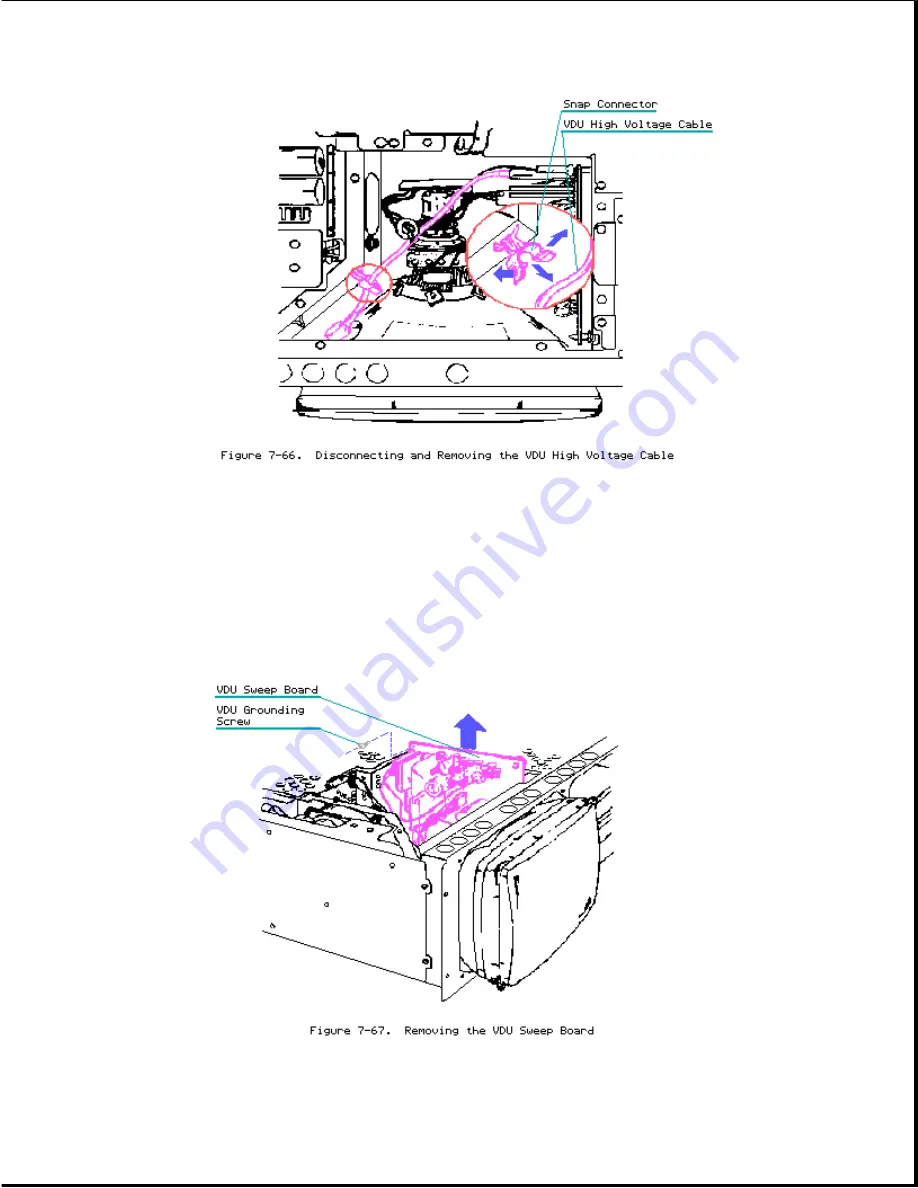
The VDU sweep board is secured to the system chassis by five PCB stand off
mounts and one screw.

Using a Torx screwdriver, remove the grounding

screw in the upper left corner of the VDU sweep board.

To remove the VDU

sweep, grasp the board and gently slide it upward until the standoffs
clear the mounting holes.

Once the VDU sweep board clears all standoffs,

slide the board out of the mounting holes and let it come to rest on the
side of the VDU (Figure 7-67).

9. 

Remove 

the 

four 

screws 

from 

the 

front 

of 

the 

video 

display 

unit

 (Figure 7-68).

Содержание Compaq Portable II

Страница 1: ...ademarks of their respective companies COMPAQ PORTABLE II PERSONAL COMPUTER MAINTENANCE AND SERVICE GUIDE Second Edition December 1990 First Edition February 1986 Manual Assy No 101206 002 Text PN 104208 002 Binder PN 104207 001 Preface This publication is intended as a reference for technicians trained to repair the COMPAQ PORTABLE II Personal Computer Summary of Text This guide contains the foll...

Страница 2: ...ptional Tools o Memory chip insertion tool o Memory chip removal tool o Diskette drive signal extension cable PN 100546 001 o Diskette drive power extension cable PN 100545 001 o Socket Torx tool kit PN 101089 001 Torx screwdrivers sizes T 15 and T 10 Adjustable socket tool with hex sockets and one Torx socket T 10 CAUTION Only trained technicians should attempt to repair this equipment All troubl...

Страница 3: ...r plug the AC power cord only into a properly grounded AC outlet Compaq Computer Corporation requires all peripheral devices be connected to this computer via shielded cables with metal RFI EMI connector hoods WIRE TYPE Multipaired overall shielded Belden 98XX Alpha 54XX or equivalent CONNECTOR HOOD RFI EMI metal shield AMP 7451 7X X or equivalent It is important that the chassis ground of any per...

Страница 4: ...quirements Voltage 120 VAC 220 240 VAC Frequency 60 Hz 50 Hz Current 3A 2 5A AC Power Cable Length 79 in 2 m Gauge 18 AWG Environmental Requirements Temperature Operating 10oC to 40oC 50oF to 104oF Nonoperating 10oC to 60oC 50oF to 140oF Shipping 30oC to 60oC 22oF to 140oF Humidity Operating 20 to 80 noncondensing Nonoperating 5 to 90 noncondensing Shock Operating 5 g 11 ms half sine Nonoperating ...

Страница 5: ...0 degree deflection High persistence green phosphor Etched surface to reduce glare Display Size 80 character by 25 line screen 40 character by 25 line screen Graphic Resolution 640 x 200 dot resolution 320 x 200 dot resolution Text Resolution 720 x 350 dot resolution Chapter 1 4 10 Megabyte Fixed Disk Drive Table 1 4 10 Megabyte Fixed Disk Drive Specifications Dimensions Height 1 7 in 4 32 cm Dept...

Страница 6: ... ms Data Transfer Rate 5 0 Mb s Type 2 Chapter 1 6 360 KByte Diskette Drive Table 1 6 360 Kbyte Diskette Drive Specifications Dimensions Height 1 1 in 2 85 cm Depth 7 9 in 20 3 cm Width 5 9 in 15 0 cm Weight 1 98 lb 0 9 kg Media Tracks per inch 48 Number of Tracks 40 when formatted with MS DOS Data Transfer Rate 250 Kb s Chapter 1 7 1 2 Megabyte Diskette Drive Table 1 7 1 2 Megabyte Diskette Drive...

Страница 7: ...e 1 9 Power Supply Specifications Input Requirements Line Voltage 102 to 132 VAC single phase 180 to 264 VAC single phase 3 0A fuse 125 VAC for 120 VAC operations 2 5A fuse 150 VAC for 220 240 VAC operation Line Frequency 47 62 Hz Cooling Forced air provided by internal 12 VDC fan Volts Direct Current Output Nominal Maximum Nominal Current Continuous Peak Regulation Voltage Amperes Current Current...

Страница 8: ...oved NOTE To test your printer during the printer test or to log errors to a printer reconnect the printer now 5 Verify that the AC power cable is connected to a usable grounded three pronged AC power outlet 6 Insert the DIAGNOSTICS diskette into drive A 7 Turn on the computer The system automatically runs POST See Section 2 2 System Problem Isolation for information on handling system problems Ch...

Страница 9: ...off the system disconnecting the device power cable and then turning on the system When the system LED lights power off the system and replace the defective subassembly NOTE For removal and replacement procedures refer to Chapter 7 5 Check the screen for a blinking cursor Do you see a cursor on the screen YES Proceed to step 6 NO Listen for an audible tone beep from the system speaker If you hear ...

Страница 10: ...creen YES This indicates the memory self test portion of POST Proceed to step 7 NO Replace the system board Restart the system problem isolation procedures 7 Did the LEDs on the mass storage device flash followed by one or two short beeps YES This indicates that POST and the SETUP utility have completed successfully The DIAGNOSTICS program should then boot and the DIAGNOSTICS menu should appear on...

Страница 11: ...Chapter 3 Setup Please consult the SUPPORT SOFTWARE MAINTENANCE AND SERVICE GUIDE for current information on SETUP ...

Страница 12: ...Chapter 4 Diagnostic Procedures Please consult the SUPPORT SOFTWARE MAINTENANCE AND SERVICE GUIDE for current information on DIAGNOSTICS ...

Страница 13: ...eps Probable Cause Recommended Action 101 I O ROM Error 1 Long Option ROM 1 Inspect ROM placement 1 Short 2 Verify correct ROM location 101 ROM Error 1 Long System ROM 3 Replace the ROM 1 Short 102 System Board None System board The following recommended action applies to error 110 System Failure None Timer failure codes 102 through 115 111 System Failure None Memory refresh Replace the system boa...

Страница 14: ...r Replace the video board Controller Failure 2 Short controller board Message Beeps Probable Cause Recommended Action 601 Diskette None Diskette 1 Replace multipurpose Controller Error controller board controller board 2 Replace multipurpose fixed disk drive controller board 602 Diskette None Diskette in Drive Replace diskette Boot Record Error A not bootable 1780 Disk 0 None Fixed disk drive Run ...

Страница 15: ...drive write read compare test failed because of a fatal error while writing For assistance in the removal and replacement of a particular subassembly see Chapter 7 Removal and Replacement Procedures Table 5 2 Processor Test Error Codes Error Codes Error Description Recommended Action 101 01 CPU test failed Replace the system board and retest for error codes 101 01 through 101 94 102 01 Numeric cop...

Страница 16: ... 113 01 103 03 DMA word controller test failed 104 01 Interrupt controller master test failed 104 02 Interrupt controller slave test failed 104 03 Interrupt controller software RTC inoperative Error Codes Error Description Recommended Action 105 01 Port 61 bit 6 not at zero Replace the system board and retest for error codes 105 02 Port 61 bit 5 not at zero 103 01 through 113 01 105 03 Port 61 bit...

Страница 17: ...est failed 111 01 Refresh detect test failed 112 01 Speed test slow mode out of range 112 02 Speed test mixed mode out of range 112 03 Speed test fast mode out of range 112 04 Speed test unable to enter slow mode 112 05 Speed test unable to enter mixed mode 112 06 Speed test unable to enter fast mode Error Codes Error Description Recommended Action 112 07 Speed test system error Replace the system...

Страница 18: ... steps apply to error codes 203 01 203 02 Error during saving program memory through 211 03 write read test 1 Replace the defective 203 03 Error during restore of program memory memory chip or in write read test option memory if installed error 204 01 Memory address test failed code 208 if an error code is accompanied 204 02 Error during saving program memory in by an XX000 BYYZZ address test code...

Страница 19: ...ry update failure 211 xx Random data pattern test 211 01 Memory random pattern test failed 211 02 Error during saving program memory and random pattern in write read test 211 03 Error during restore of program memory and random pattern in write read test Table 5 4 Keyboard Test Error Code Error Codes Error Description Recommended Action 301 01 Keyboard short test 8042 self test The following steps...

Страница 20: ... code from keyboard connections to system board 304 04 No keyboard make code observed 3 Replace the keyboard and retest 304 05 Unable to disable typematic feature 4 Replace the system board and retest 304 06 Unable to return to normal mode Table 5 5 Parallel Printer Interface Test Error Codes Error Codes Error Description Recommended Action 401 01 Printer failed or not connected The following step...

Страница 21: ... 402 15 Printer interrupt loopback data and control register failed 402 16 Printer unexpected interrupt received 403 01 Printer pattern test failed 498 00 Printer failed or not connected Table 5 6 Video Display Unit Test Error Codes Error Codes Error Description Recommended Action 501 01 Video controller test failed The following steps apply to error codes 501 01 502 01 Video memory test failed th...

Страница 22: ...ID drive types test failed The following steps apply to error codes 600 xx 601 xx Diskette format failed through 614 xx 602 xx Diskette read test failed NOTE If the COMPAQ Enhanced Color Graphics 603 xx Diskette write read compare test Board is installed check failed the interrupt setting 604 xx Diskette random seek test failed 1 Replace the diskette and retest 605 xx Diskette ID media failed 2 Ch...

Страница 23: ...ontroller board or the multipurpose 614 22 Failed to clear change line status controller board 3 Replace the diskette 614 23 Failed to set drive type in ID media power and signal cables and retest 614 24 Failed to read diskette media 4 Replace the multipurpose fixed disk drive 614 25 Failed to verify diskette media controller board or multipurpose controller 614 26 Failed to read media in speed te...

Страница 24: ...01 03 Serial port test address line fault serial parallel interface board 1101 04 Serial port test data line fault multipurpose fixed disk drive controller board 1101 05 Serial port test UART control signal or the multipurpose failure controller board and retest 1101 06 Serial port test UART THRE bit 2 Replace the failure serial parallel interface board 1101 07 Serial port test UART DATA READY mul...

Страница 25: ... Line input or UART failure 1 Refer to modem documentation for 1201 03 Address line fault correct setup procedures 1201 04 Data line fault 2 Check the modem line 3 Replace the modem and 1201 05 UART control signal failure retest 1201 07 UART DATA READY bit failure 1201 08 UART TX RX buffer failure 1201 09 INTERRUPT circuit failure 1201 10 COM1 set to invalid interrupt 1201 11 COM2 set to invalid i...

Страница 26: ...analog loopback answer mode 1202 22 Timed out waiting for modem response analog loopback answer mode 1202 23 Exceeded data block retry limit analog loopback answer mode Error Codes Error Description Recommended Action 1203 xx Modem External Termination test The following apply to error codes 1201 xx 1203 01 Modem external TIP RING failure through 1210 xx 1203 02 Modem external DATA TIP RING failur...

Страница 27: ...te mode 1210 13 Modem exceeded data block retry limit analog loopback originate mode 1210 14 DRIVER RECEIVER data failure 1210 15 Modem detection failure 1210 16 Modem ROM checksum failed 1210 17 Tone detection failure 1210 21 Modem timed out waiting SYNC analog loopback answer mode 1210 23 Modem exceeded data block for retry limit analog loopback answer mode Table 5 10 Fixed Disk Drive Test Error...

Страница 28: ...iption Recommended Action 17yy xx Invalid fixed disk drive type failed The following steps apply to error codes 1700 xx 17yy 01 Exceeded maximum soft error limit through 1716 xx 17yy 02 Exceeded maximum hard error limit 1 Check switch and jumper settings on the fixed 17yy 03 Previously exceeded maximum soft error disk drive controller limit board multipurpose fixed disk drive 17yy 04 Previously ex...

Страница 29: ...Failed file I O write test board multipurpose fixed disk drive 17yy 5l Failed file I O read test controller board or multipurpose controller 17yy 52 Failed file I O compare test board and retest 4 Replace the fixed disk drive and retest 5 Replace the system board and retest 17yy 53 Failed drive head register test 17yy 54 Failed digital input register test Error Codes Error Description Recommended ...

Страница 30: ...or Description Recommended Action 2402 01 Video memory test failed The following steps apply to error codes 2402 01 2403 01 Video attribute test failed through 2416 01 2404 01 Video character set test failed 1 Verify the switch settings 2405 01 Video 80 x 25 mode 9 x 14 character 2 Replace the COMPAQ cell test failed Enhanced Color Graphics Board ROM and retest 2406 01 Video 80 x 25 mode 8 x 8 cha...

Страница 31: ...2 Replace the COMPAQ 2420 01 ECG attribute test failed Enhanced Color Graphics Board ROM 2421 01 ECG 640 x 200 graphics mode test 3 Replace the COMPAQ failed Enhanced Color Graphics Board and retest 2422 01 ECG 640 x 350 16 Color Set test 4 Replace the system failed board and retest 2423 01 ECG 640 x 350 64 Color Set test failed 2424 01 ECG Monochrome Text Mode test failed 2425 01 ECG Monochrome G...

Страница 32: ... caused by to a failure in the memory support circuitry not the memory The memory error code points to a specific memory address The physical location of the memory address depends on the type of system the number and type of memory boards installed and the type of memory device used 64K x 1 Bit RAMs or 256K x 1 Bit RAMs Tables 5 14 through 5 17 identify which memory device to replace when the sys...

Страница 33: ...solation Map for System Boards using 64K RAMs and 256K RAMs Memory error codes are in the format XX000B YYZZ XX is the memory segment of detected error 000 is always equal to 000 not used B Byte bank location Low B 0 High B 1 ...

Страница 34: ...Personal Computer System Boards Version 1 and 2 For information on removing and replacing memory chips contained on the system board refer to Chapter 7 in this guide Table 5 14 Version 1 System Board using 64K RAMs 0 256 Kbytes XX 00 Bank 0 Data Bit B 0 B 1 YY or ZZ Low High Required Action 00 U37 U38 Replace memory chip 01 U30 U31 Replace memory chip 02 U25 U26 Replace memory chip 04 U21 U22 Repl...

Страница 35: ...y chip 08 U41 U42 Replace memory chip 10 U33 U34 Replace memory chip 20 U25 U26 Replace memory chip 40 U18 U19 Replace memory chip 80 U10 U11 Replace memory chip XX 02 Bank 1 Data Bit B 0 B 1 YY or ZZ Low High Required Action 00 U40 U43 Replace system board 01 U31 U16 Replace system board 02 U31 U16 Replace system board 04 U31 U16 Replace system board 08 U31 U16 Replace system board 10 U23 U8 Repl...

Страница 36: ...ta Bit B 0 B 1 YY or ZZ Low High Required Action 00 U41 U42 Replace system board 01 U51 U52 Replace system board 02 U51 U52 Replace system board 04 U51 U52 Replace system board 08 U51 U52 Replace system board 10 U46 U47 Replace system board 20 U46 U47 Replace system board 40 U46 U47 Replace system board 80 U46 U47 Replace system board Table 5 17 Version 2 System Board using 256K RAMs 0 640 Kbytes ...

Страница 37: ...Isolation Map for the 512 1536 Kbyte System Memory Board Mapped into the 1 to 2 5 Megabyte Memory Space 256K x 1 Bit RAMs NOTE This isolation map is valid for a system memory board that uses 256K x 1 bit RAMs Memory error codes are in the format XX000B YYZZ XX equals the 128 Kbyte memory segment where an error is detected 000 is always equal to 000 not used B Byte bank location Low B 0 High B 1 YY...

Страница 38: ... U23 Replace system memory board 01 U31 U7 Replace system memory board 02 U32 U8 Replace system memory board 04 U54 U51 Replace system memory board 08 U39 U15 Replace system memory board 10 U40 U16 Replace system memory board 20 U53 U50 Replace system memory board 40 U48 U24 Replace system memory board 80 U52 U49 Replace system memory board XX 18 1A 1C 1E Bank 3 Data Bit B 0 B 1 YY or ZZ Low High ...

Страница 39: ...eplace memory chip 80 U46 U22 Replace memory chip XX 20 22 24 26 Bank 4 Data Bit B 0 B 1 YY or ZZ Low High Required Action 00 U41 U17 Replace memory chip 01 U25 U1 Replace memory chip 02 U26 U2 Replace memory chip 04 U27 U3 Replace memory chip 08 U33 U9 Replace memory chip 10 U34 U10 Replace memory chip 20 U35 U11 Replace memory chip 40 U42 U18 Replace memory chip 80 U43 U19 Replace memory chip ...

Страница 40: ...yed to an illustration o Part Number to be used when ordering parts from Compaq Computer Corporation o Description name of the particular part or parts kit NOTE When several parts have the same part number the parts are available only as part of a kit Chapter 6 1 Compaq Portable II Personal Computer Table 6 1 COMPAQ PORTABLE II Personal Computer Item Part Number Description 1 107899 001 Chassis Co...

Страница 41: ...scription 1 107899 001 Chassis Cover 2 104081 001 Chassis Assembly 3 104198 001 Front Bezel 4 104059 001 Drive Bezel 5 104050 001 Blank Drive Bezel third height 6 Brightness Knob Assembly 7 101155 001 AC Power Cord 8 102930 001 3 A AC Line Fuse Quantity 40 100228 002 3 A AC Line Fuse Quantity 1 Contained in the Miscellaneous Hardware Kit Spare PN 104270 001 See Table 6 7 ...

Страница 42: ... Part number no longer available Chapter 6 3 Common Chassis Table 6 3 COMPAQ PORTABLE II Personal Computer Common Chassis Item Part Number Description ...

Страница 43: ...le Underlay 11 112693 001 replaced by 197458 001 2400 Baud Internal Modem 12 104081 001 Chassis Assembly 13 Torx 6 32 x 3 8 Screw 14 104185 001 Speaker Brightness Potentiometer Assembly 15 Brightness Knob Contained in the Miscellaneous Hardware Kit Spare PN 104270 001 See Table 6 7 Part number no longer available Item Part Number Description 16 104183 001 10 Megabyte Fixed Disk Drive 104405 001 20...

Страница 44: ...ive C 6 Inch 31 104184 001 360 Kbyte flip door Diskette Drive 107360 001 360 Kbyte push button Diskette Drive 104479 001 1 2 Megabyte flip door Diskette Drive 107359 001 1 2 Megabyte push button Diskette Drive 109595 001 1 44 Megabyte Diskette Drive 106558 001 Weitek 287 Coprocessor 8 MHz 105151 001 150 ns DRAM Chips 256K x 1 105152 001 150 ns DRAM Chips 64K x 1 105035 001 System ROM Contained in ...

Страница 45: ...e Device Access Plate 2 104079 001 Mass Storage Device Access Plate 3 Torx 4 40 x 1 4 Screw 4 130770 001 Board Slots Access Plate 5 104081 001 Chassis Assembly 6 104098 001 Memory Expansion Access Plate 7 104099 001 Cable Tray Access Plate Contained in Miscellaneous Hardware Kit Spare PN 104270 001 Part number no longer available Chapter 6 5 Monitor ...

Страница 46: ... 3 Mounting Screws 4 4 106568 001 Color Monitor external Included in the Cable Kit See Table 6 6 Included in the Miscellaneous Hardware Kit Spare PN 104270 001 No longer available Refer to Table 6 7 Chapter 6 6 Cable Kit Table 6 6 COMPAQ PORTABLE II Personal Computer Cable Kit PN 104191 001 No longer available Description Quantity 1 Diskette Drive Power Cable 1 2 Video Display Signal Cable 1 ...

Страница 47: ...ption Quantity Monitor Drive Enclosure Screw 25 Screw Covers 25 Drive Shoulder Bolt 10 Drive Vibration Isolators 5 Ty Wrap 3 4 in wide 3 7 8 in long 18 100 PCB Board Guide 5 Fixed Disk Drive LED Cable 2 Brightness Knob 5 PCB Board Retainers 2 Push Mount Fasteners 5 Fan Well Nuts 5 High Voltage Monitor Grommet 2 System Board Connector Grommet 5 Keyboard Rubber Foot 10 Option Board Locking Standoffs...

Страница 48: ...wing steps 1 Turn off the computer 2 Close the keyboard and secure it by sliding the latches to the LOCK position Figure 7 1 and folding the keyboard feet in place 3 Disconnect any peripheral devices printers monitors and so on from the computer 4 Disconnect the AC power cord from the AC outlet and from the computer Figure 7 2 ...

Страница 49: ...AC Power Fuse To remove the AC power fuse complete the following steps 1 Complete the preparation procedures see Section 7 1 2 Slide open the AC power compartment to expose the line filter ON OFF switch Figure 7 3 ...

Страница 50: ...ut of the casing Figure 7 4 4 When the fuse box is removed locate the spare fuse provided in the holding area in the fuse box Figure 7 5 Lift the fuse out and replace it with the spare fuse 5 Slide the fuse box back into place Press the cover in until you feel it snap into place NOTE Use only a fuse with a 3 Ampere current rating ...

Страница 51: ...plete the preparation procedure see Section 7 1 2 Place the computer keyboard side down on a level work surface Slide open the AC power access panel and the peripheral connector access panels Using a Torx screwdriver remove the mounting screws from the AC power and peripheral connector access areas Figures 7 6 and 7 7 ...

Страница 52: ...asping it close to the AC power and peripheral connector access panels and sliding the cover towards you Slide it completely off the system chassis Figure 7 8 and set it aside NOTE The outer access casing is flexible and will bend as needed ...

Страница 53: ...nd 3 Chapter 7 4 Keyboard Assembly To remove the keyboard assembly complete the following steps 1 Remove the cable tray access plate see Section 7 13 2 Disconnect the keyboard cable connector from the J116 socket connector on the system board Figure 7 9 ...

Страница 54: ...puter so that it rests flatly against the work surface Figure 7 10 4 Unlock the keyboard latches and gently slide the keyboard cable from inside the computer system chassis Figure 7 11 Remove the keyboard from the computer system chassis ...

Страница 55: ...rse steps 1 through 4 Chapter 7 5 Front Bezel To remove the front bezel complete the following steps 1 Remove the keyboard assembly see Section 7 4 2 Remove the brightness control knob by gently pulling it from the front bezel Figure 7 12 ...

Страница 56: ...Lift the rear portion of the computer so that it rests firmly on the front bezel Figure 7 13 4 Using a Torx screwdriver remove the six screws that secure the front bezel to the system chassis Figure 7 14 ...

Страница 57: ...ently pull the front bezel from the system chassis Figure 7 15 To replace the front bezel reverse steps 1 through 5 Chapter 7 6 Power Supply Subassembly Chassis The power supply subassembly chassis consists of the following assemblies ...

Страница 58: ...e the power supply subassembly chassis complete the following steps 1 Remove the outer access casing see Section 7 3 2 Place the computer on its side see Figure 7 16 3 Using a Torx screwdriver loosen DO NOT REMOVE the nine mounting screws that secure the power supply chassis to the system chassis Figure 7 17 ...

Страница 59: ...4 Remove only the two screws indicated in Figure 7 18 ...

Страница 60: ...d lift the front portion of the chassis until the entire power supply chassis is free of the system chassis Figure 7 19 NOTE Because the power supply connects directly to the system board be careful when removing the power supply subassembly chassis 6 To completely remove the power supply subassembly chassis from the ...

Страница 61: ...upply subassembly chassis reverse steps 1 through 6 Chapter 7 7 Fan Assembly To remove the fan assembly complete the following steps 1 Remove the power supply subassembly chassis see Section 7 6 2 Cut the two cable ties that secure the fan assembly power cable to the system chassis 3 Using a Phillips screwdriver remove the two mounting screws and lift the fan assembly from the system chassis Figur...

Страница 62: ...r 7 8 Automatic Power Switching Board APS 1 Remove the power supply subassembly chassis see Section 7 6 NOTE Carefully remove all three connections to the APS board when removing the power supply chassis Refer to Figure 7 22 for an illustration of the APS board ...

Страница 63: ...together one at a time At the same time carefully lift that portion of the APS board from the system chassis Repeat this procedure until all board standoffs have been disconnected from the APS board then lift and remove the APS board from the system chassis Figure 7 23 To replace the APS Board complete the following steps ...

Страница 64: ...re to reconnect the fan Do not pinch the harness wires between the power supply subassembly and the chassis this could interfere with the cooling system and result in overheating 4 Reinstall the power supply subassembly chassis see Section 7 6 Chapter 7 9 High Voltage Access Plate The high voltage access plate is located just above the video monitor and power supply assemblies To remove the high v...

Страница 65: ...assis To replace the high voltage access plate reverse steps 1 through 3 Chapter 7 10 Board Slots Access Plate The board slots access plate is located at the rear of the computer and covers all installed controller and option boards To remove the board slots access plate complete the following steps 1 Remove the outer access casing see Section 7 3 2 Using a Torx screwdriver loosen DO NOT REMOVE th...

Страница 66: ... of the system chassis and covers all installed mass storage devices To remove the mass storage device access plate complete the following steps 1 Remove the outer access cover See Section 7 3 NOTE It is not necessary to remove the mass storage device access plate before removing the mass storage device enclosure 2 Using a Torx screwdriver remove the eight mounting screws that secure the mass stor...

Страница 67: ... the mass storage device access plate reverse steps 1 through 3 Chapter 7 12 System Memory Board Access Plate To remove the system memory board access plate complete the following steps 1 Remove the outer access casing see Section 7 3 2 Turn over the system chassis as illustrated in Figure 7 28 ...

Страница 68: ... system memory board access plate to the system chassis Remove only the one mounting screw indicated in Figure 7 29 4 Carefully lift and remove the system memory board access plate from the system chassis Figure 7 29 To replace the system memory board access plate reverse steps 1 through 4 ...

Страница 69: ...sing see Section 7 3 2 Remove the system memory board access plate see Section 7 12 3 Turn over the system chassis as illustrated in Figure 7 30 4 Using a Torx screwdriver loosen DO NOT REMOVE the seven Torx screws that secure the cable tray access plate to the system chassis Remove only the two mounting screws noted in Figure 7 31 ...

Страница 70: ...assis To replace the cable tray access plate reverse steps 1 through 5 Chapter 7 14 Multipurpose Controller Board The Multipurpose Controller Board is located in slot J104 on the system board Figure 7 32 To remove the multipurpose controller board complete the following steps ...

Страница 71: ... 7 10 2 Disconnect the mass storage device signal cable s as shown in Figure 7 33 NOTE If a fixed disk drive is installed in the system chassis you must disconnect two signal cables 3 Using a Torx screwdriver remove the board retaining screw Carefully ...

Страница 72: ... of the system board Figure 7 34 To replace the Multipurpose Controller Board reverse steps 1 through 3 Chapter 7 15 Video Display Controller Board The Video Display Controller Board is located in slot J103 on the system board Figure 7 35 ...

Страница 73: ... the board slots access plate see Section 7 10 2 Remove the retaining screw that secures the Video Display Controller Board Then disconnect the video display signal cable Figure 7 36 3 Carefully lift the board up and out of its J103 connector location on the system board Figure 7 37 ...

Страница 74: ...he back two slots of the system chassis To remove a COMPAQ 512 2048 Kbyte Memory Expansion Board or any other option board installed in the computer complete the following steps 1 Remove the outer access casing See Section 7 3 2 Disconnect any signal cables connected to the board 3 Remove the retaining screw that secures the board to the system chassis 4 Carefully lift the board up and out of its ...

Страница 75: ...mplete the following steps 1 Remove the outer access casing see Section 7 3 2 Remove the board slots access plate see Section 7 10 3 Remove all controller and option boards installed see Sections 7 14 through 7 16 4 Using a Torx screwdriver remove the two mounting screws that secure the handle to the system chassis and remove the handle system chassis Figure 7 39 ...

Страница 76: ... 000318 and version 2 Assy No 000324 The two system boards differ in shape memory chip locations and jumper locations Figures 7 40 and 7 41 Functionally both versions are identical however the version 2 system board contains three gate array devices that consolidate the functions of several devices from the earlier version making a smaller system board possible ...

Страница 77: ...he power supply subassembly chassis see Section 7 6 2 Remove the board slots access plate see Section 7 10 3 Remove all controller and option boards installed see Sections 7 14 through 7 16 4 Using Figure 7 42 as a reference disconnect the mass storage device power cable ...

Страница 78: ...d access plate see Section 7 12 6 Remove the cable tray access plate see Section 7 13 7 Using Figure 7 43 as a reference disconnect the keyboard power cable the video display unit power cable and the speaker brightness control cable ...

Страница 79: ... longer available should be replaced with an assembly containing a longer wiring harness Spare part kits containing version 2 boards include a speaker brightness potentiometer assembly NOTE Be sure to pay special attention to the system board guide clamp at the rear of the chassis Chapter 7 19 Battery WARNING The lithium battery may explode if mishandled or stored improperly Do not abuse disassemb...

Страница 80: ...or Figure 7 45 CAUTION Make sure the polarity is correct when replacing the battery Improper installation of the battery can cause damage to the computer To replace the battery complete the following steps 1 Replace the battery in the snap in connector 2 Replace the cable tie 3 Replace the 512 1536 Kbyte System Memory Board access plate see Section 7 12 Chapter 7 20 512 1536 KByte System Memory Bo...

Страница 81: ...ected from the system memory board 4 Lift the disconnected memory board from the system board Figure 7 46 To replace the memory board reverse steps 1 through 4 Chapter 7 21 Memory Option COMPAQ PORTABLE II Personal Computer memory chips can be installed on the system board the 512 2048 Kbyte Memory Expansion Board or the 512 1536 Kbyte System Memory Board To remove a memory chip complete the follo...

Страница 82: ...dure refer to Section 7 18 o For the 512 1536 Kbyte System Memory Board removal and replacement procedure refer to Section 7 20 NOTE The RAM and ROM chip locations on the system boards differ from those on the memory boards See Figures 7 47 through 7 50 ...

Страница 83: ......

Страница 84: ...2 Using an IC removal tool remove the defective RAM or ROM chip s Figure 7 51 3 Using a special IC insertion tool replace the defective RAM or ROM chip s Figure 7 52 ...

Страница 85: ...the SUPPORT SOFTWARE MAINTENANCE AND SERVICE GUIDE for current information on DIAGNOSTICS Chapter 7 22 Mass Storage Device Subassembly Mass storage device subassemblies for the COMPAQ PORTABLE II Personal Computer consist of fixed disk drives and diskette drives Refer to Figure 7 53 for the location of each type of mass storage device subassembly ...

Страница 86: ...sure complete the following steps 1 Remove the outer access casing see Section 7 3 2 Remove all installed controller and option boards see Sections 7 14 through 7 16 3 Using a screwdriver gently pry the drive bezel from the front bezel Figure 7 54 This exposes the installed mass storage devices ...

Страница 87: ...e device enclosure These screws secure the mass storage device subassembly enclosure to the system chassis Figure 7 55 5 Slide the mass storage device subassembly enclosure forward a few inches by reaching into the open system chassis area and pushing the enclosure forward This action will expose the mass storage power cables Figure 7 56 ...

Страница 88: ... diskette drive and fixed disk drive power cable from the system board Figure 7 57 7 Grasp the sides of the mass storage device subassembly enclosure firmly and slide the enclosure out of the system chassis Figure 7 58 ...

Страница 89: ...e assembly 1 Remove the mass storage device subassembly enclosure see Section 7 22 2 Using a Torx screwdriver remove the two shoulder bolts and vibration isolators from either side of the mass storage device subassembly enclosure Slide the fixed disk drive assembly enclosure out of the mass storage device subassembly Figure 7 59 ...

Страница 90: ...omplete the following steps 1 Remove the mass storage device subassembly enclosure see Section 7 22 2 Using a Torx screwdriver remove the two shoulder bolts that secure the diskette disk drive assembly from either side of the mass storage device subassembly enclosure Figure 7 60 3 Slide the diskette drive assembly out of the mass storage device subassembly enclosure Figure 7 60 ...

Страница 91: ...new diskette drive assembly Chapter 7 23 Speaker and Brightness Potentiometer To remove the speaker and brightness potentiometer 1 Remove the cable tray access plate see Section 7 13 2 Remove the mass store device enclosure see Section 7 22 3 Remove the front bezel see Section 7 5 4 The speaker is secured to the system chassis by a snap in mount and a toe in mount that extend through the system ch...

Страница 92: ... unscrewing the nut that secures it to the system chassis then push the brightness potentiometer out of the system chassis Figure 7 62 To replace the speaker and the brightness potentiometer reverse steps 1 through 5 Chapter 7 24 Video Display Unit ...

Страница 93: ...he video display unit VDU complete the following steps 1 Remove the keyboard assembly see Section 7 4 2 Disconnect the VDU power cable Figure 7 63 3 Lower the computer so that it appears as illustrated Figure 7 64 ...

Страница 94: ...ct the VDU signal cable from the VDU Figure 7 65 7 The VDU high voltage cable is secured to the system chassis by a push mount with a snap connector at the end Disconnect the VDU high voltage cable by first unsnapping the push mount and then removing the cable from its place inside the connector Figure 7 66 ...

Страница 95: ...t corner of the VDU sweep board To remove the VDU sweep grasp the board and gently slide it upward until the standoffs clear the mounting holes Once the VDU sweep board clears all standoffs slide the board out of the mounting holes and let it come to rest on the side of the VDU Figure 7 67 9 Remove the four screws from the front of the video display unit Figure 7 68 ...

Страница 96: ...ping the display screen and the VDU sweep board and then sliding the unit until it is out of the system chassis Figure 7 69 If replacement is necessary this unit may be shipped back to Compaq Computer Corporation packed only in a Compaq Spare VDU box ...

Страница 97: ... VDU assembly replace the two top front mounting screws first This helps align the screen correctly CAUTION The video display unit is fragile be careful when handling it Be careful not to disturb the VDU adjustment potentiometers on the VDU sweep board and not to break the display tube ...

Страница 98: ...s Figure 8 1 shows the jumper locations on the COMPAQ PORTABLE II Version 1 system board Refer to Table 8 1 when setting the jumpers on this board Figure 8 2 shows the jumper locations on the COMPAQ PORTABLE II Version 2 system board Refer to Table 8 1 when setting the jumpers on this board ...

Страница 99: ...S2 G MS1 G 512 Kbyte memory installed MS2 V MS1 V 640 Kbyte memory installed default MS2 V MS3 Memory Board MS3 1 0 1 Megabyte memory recognized or V 512 1536 Kbyte MS3 1 5 1 5 Megabytes memory recognized memory selection or G default Chapter 8 2 512 2048 KByte Memory Expansion Board Jumper Settings The jumper settings on the 512 2048 Kbyte Memory Expansion Board correspond to the amount of random...

Страница 100: ... 2048 Kbyte Memory Expansion Board Table 8 2 512 2048 Kbyte Memory Expansion Board Jumper Settings Settings Address Range E1 to E2 E5 to E6 1 to 3 megabyte E1 to E2 E4 to E5 2 5 to 4 5 megabyte Memory address range is dependent on system memory board configuration ...

Страница 101: ...nks 1 2 3 and 4 2048 Kbytes Chapter 8 3 360 KByte Diskette Drive Switch Settings Figure 8 4 shows the COMPAQ PORTABLE II 360 Kbyte Diskette Drive This diskette drive contains an 8 position switch Refer to Table 8 4 when setting switch positions Table 8 4 360 Kbyte Diskette Drive Switch Settings Switch Position Function Switch Setting 1 Reserved ON 2 Reserved OFF 3 Reserved ON 4 Reserved OFF 5 Rese...

Страница 102: ...7 when setting the switches and jumpers Table 8 5 Multipurpose Controller Board Switch and Jumper Settings Jumper Pin 1 to Pin 2 Pin 2 to Pin 3 J1 Secondary diskette controller address Primary diskette controller address default J2 Serial interface COM1 Serial interface COM2 J4 Serial interface IRQ4 Serial interface IRQ3 J3 Disable parallel interface Enable parallel interface J2 and J4 must be cha...

Страница 103: ...controller address default Open connectors on right Secondary diskette controller address SW1 1 ON Enable fixed disk drive OFF Disable fixed disk drive SW1 2 ON Enable parallel interface default OFF Disable parallel interface SW1 3 ON Enable serial interface default OFF Disable serial interface SW1 4 OFF Reserved SW1 1 reserved on Assy No 000181 boards SW1 3 reserved on Assy No 000181 001 all Revi...

Страница 104: ...0 2 OFF Disable high speed transfer rates for systems without 1 2 megabyte diskette drive ON Enable high speed transfer rates for systems with 1 2 megabyte diskette drive default SW500 3 OFF Enable fixed disk drive default ON Disable fixed disk drive SW500 4 OFF Serial interface COM1 IRQ4 default ON Serial interface COM2 IRQ3 SW500 5 OFF Enable serial interface default ON Disable serial interface ...

Страница 105: ...ard Figure 8 10 shows the jumper locations for the Fixed Disk Drive Controller Board Assy No WD1003IWH Refer to Table 8 8 when setting the jumpers Table 8 8 Fixed Disk Drive Controller Board Jumper Settings Assy No WD1003IWH Jumper Pin Function ...

Страница 106: ... Video Display Controller Board Refer to Tables 8 9 and 8 10 when setting the jumpers Table 8 9 Video Display Controller Board Switch and Jumper Settings Assy Nos 000031 000160 and 000345 J3 J5 Function 2 3 2 3 Enable RGBI and composite video high scan 1 2 1 2 Disable RGBI and composite video high scan default Table 8 10 Video Display Controller Board Jumper Settings Assy No 000525 Jumper Location...

Страница 107: ... J3 J5 RGB enable disable high scan Pin 1 to Pin 2 Disables RGB and composite video Pin 2 to Pin 3 RGB and composite video enable ...

Страница 108: ...Jumper Settings Figures 8 15 and 8 16 show the switch and jumper locations on the Enhanced Color Graphics Boards Refer to Table 8 11 when setting the switches and jumpers Table 8 11 Enhanced Color Graphics Board Switch Settings Assy Nos 000410 and 000471 ...

Страница 109: ...lor or COMPAQ 640 x 350 Dual Mode ON OFF ON ON COMPAQ Color Compatible 80 x 25 Color Enhanced Color or COMPAQ 640 x 200 Dual Mode OFF ON ON ON RGBI Color or COMPAQ Dual 80 x 25 Color Mode 640 x 200 ON ON ON ON RGBI Color or COMPAQ Dual 40 x 25 Color Mode 320 x 200 OFF ON OFF ON COMPAQ Dual Mode 80 x 25 Monochrome 720 x 350 SW2 Settings 1 2 3 4 5 6 Monitor Type OFF OFF COMPAQ Color or Compatible En...

Страница 110: ... Jumper JP3 Pins Address Select 1 2 3xxh default 2 3 2xxh ...

Страница 111: ... 4 5 6 Function OFF Reserved ON Enable asynchronous interface OFF Disable asynchronous interface ON ON Parallel printer interface LPT1 OFF ON Parallel printer interface LPT2 ON OFF Parallel printer interface LPT3 OFF OFF Disable parallel printer interface ON ON Asynchronous interface COM1 OFF ON Asynchronous interface COM2 Table 8 13 Serial Parallel Interface Board Switch Settings Assy No 000990 1...

Страница 112: ...deo display adjustment on your COMPAQ PORTABLE II Personal Computer To complete the adjustment procedure the following equipment is required o All tools normally required to service a COMPAQ PORTABLE II Personal Computer see Preface o DIAGNOSTICS diskette o Set of standard television adjustment tools o COMPAQ PORTABLE II Personal Computer display template PN 100686 003 The video display adjustment...

Страница 113: ...Computer and load the DIAGNOSTICS program Refer to Chapter 4 in this guide for more information on the COMPAQ PORTABLE II Personal Computer DIAGNOSTICS program 4 Select the video display alignment procedure from the video display unit test menu and press ENTER After you select the video display adjustment procedure the screen will appear completely blank This is normal program operation 5 Turn the...

Страница 114: ...the BRITE control until the screen raster appears on the display Check this display to make sure it is not tilted in any way Figure 8 21 NOTE Do not use excessive force when making adjustments on the video display unit 7 Turn the brightness control knob until the raster disappears ...

Страница 115: ...ithin the range specified on the adjustment template Width may change between high and low resolution mode and should be adjusted appropriately Figure 8 22 NOTE When making adjustments on the video display unit do not use excessive force 10 If the characters on your display are not sharp and clear a focus adjustment is necessary Using a plastic adjustment tool adjust the potentiometer labeled FOCU...

Страница 116: ... Figure 8 24 See Chapter 4 in this guide for more information on the VDU adjustment program 12 Two adjustments control the character height The first is the master height control potentiometer which controls the height of characters in both the high and low resolution modes The second is the high scan height control potentiometer which controls the height of characters ...

Страница 117: ...lace the display in the high resolution mode Press and hold the CTRL and ALT keys while pressing the greater than key Then release all three keys Using the adjustment tool adjust the high scan height control potentiometer so that all characters appear at the desired height 15 If characters near the top of the display appear taller or shorter than those near the bottom of the display a linearity ad...

Страница 118: ...8 26 for the locations of both the master video center and high scan video center control potentiometers NOTE Do not use excessive force when making adjustments on the video display unit 18 Use the CTRL ALT command to place the display in the low resolution graphics mode Use the adjustment tool and adjust the master video center control potentiometer so that the display is in the center of the scr...

Отзывы: