Compaq 5000 Series Скачать руководство пользователя страница 36

36

   R

EPLACING


THE

 S

YSTEM

 B

OARD

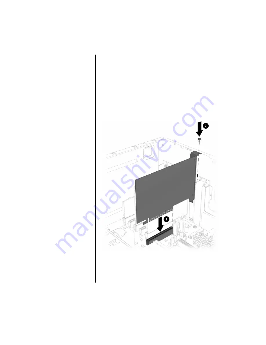
VII. Replacing the Graphics Card

To replace the graphics card, complete the following 
procedure:

1. Align the graphics card with the AGP slot 

1

 on the system 

board. Insert the card carefully and firmly into the AGP 
slot (see Figure 7-1). 

2. Replace the screw 

2

 to secure the graphics card to the 

chassis (see Figure 7-1).

Figure 7-1

Содержание 5000 Series

Страница 1: ...End User Replaceable Parts Program Replacing a System Board 5000 and 7000 Series ...

Страница 2: ...IENT IN NO EVENT SHALL COMPAQ BE LIABLE FOR ANY DIRECT CONSEQUENTIAL INCIDENTAL SPECIAL PUNITIVE OR OTHER DAMAGES WHATSOEVER INCLUDING WITHOUT LIMITATION DAMAGES FOR LOSS OF BUSINESS PROFITS BUSINESS INTERRUPTION OR LOSS OF BUSINESS INFORMATION EVEN IF COMPAQ HAS BEEN ADVISED OF THE POSSIBILITY OF SUCH DAMAGES THE FOREGOING SHALL APPLY REGARDLESS OF THE NEGLIGENCE OR OTHER FAULT OF EITHER PARTY AN...

Страница 3: ... in cards The add in cards such as modem sound and graphics are mounted upright in slots on the system board along with other internal devices that connect directly to the system board Introduction Your Compaq Presario Internet PC has an Easy Access panel that makes accessing the internal parts easy This document describes how to remove and replace the system board see Figure 1 1 Figure 1 1 Import...

Страница 4: ...elivered to you or the original One Year Limited Warranty that came with your Compaq Presario Preparing Your Computer for Disassembly Before beginning the removal and replacement procedure complete the following procedure 1 Remove any diskette or compact discs CDs from the computer 2 Turn off the computer and any peripheral devices connected to your computer see Figure 1 2 3 Disconnect the power c...

Страница 5: ... Turn off the computer using the Power button see Figure 1 2 Figure 1 2 2 Disconnect the power cord from the electrical outlet 1 and from the computer 2 see Figure 1 3 Failure to disconnect the power from the computer may result in personal injury Figure 1 3 ...

Страница 6: ... the side access panel Locate the latch 2 directly below the screw press it down and hold the latch in the down position see Figure 2 1 Figure 2 1 Important Some models may not have a screw 1 This screw is used for shipping purposes only 2 Grab the handle and slide the side panel from the chassis see Figure 2 2 Caution Before doing any work inside your computer ground yourself by touching a metal ...

Страница 7: ...BOARD 7 III Locating the System Board Turn the computer on its side open side facing up and locate the system board see Figure 3 1 Figure 3 1 Important The location of the system board components may vary slightly by model ...

Страница 8: ... THE SYSTEM BOARD IV Removing the Data Cables from the System Board Disconnect the diskette drive 1 hard drive 2 and CD ROM 3 CD RW 3 and or DVD drive 3 data cables from the system board see Figure 4 1 Figure 4 1 ...

Страница 9: ...ith the computer on its side open side facing up locate the memory module 2 see Figure 5 1 2 Press outward on the release latches found at each end of the memory slot 1 Lift the memory module 2 from the memory slot 1 see Figure 5 1 The number of memory modules may vary depending upon your system s configuration Figure 5 1 ...

Страница 10: ...k Assembly See the illustration below for the location of the heatsink lock tabs 1 heatsink power supply fan cable 2 heatsink 3 microprocessor interface 4 see Figure 6 1 Figure 6 1 Important The location of the microprocessor heatsink assembly may vary slightly by model ...

Страница 11: ...the computer on its side open side facing up locate the microprocessor see Figure 7 1 2 Disconnect the heatsink power supply fan cable 1 see Figure 7 1 3 Pull forward on the heatsink lock tabs 2 located at the base to release the processor Figure 7 1 The microprocessor may still be hot if the computer was recently used Allow the microprocessor to cool before removing ...

Страница 12: ...12 REPLACING THE SYSTEM BOARD 4 Push in the release tabs 1 on the end of the processor and lift the processor 2 from the chassis see Figure 7 2 Figure 7 2 ...

Страница 13: ...of expansion cards This chart will help you to identify the different types of expansion cards such as a modem 1 and a Network Interface Card NIC 2 that can be added to your computer see Figure 8 1 Figure 8 1 rear view of chassis Important These expansion cards may fit into any available PCI slot The number of PCI slots may vary by model ...

Страница 14: ...e expansion card s see Figure 9 1 2 Remove the screw 1 securing the expansion card see Figure 9 1 Important Keep the screw 1 that secured the card to the chassis You will need it when replacing the card 3 Using a gentle rocking motion pull the expansion card from the PCI slot 2 on the system board see Figure 9 1 Figure 9 1 ...

Страница 15: ...h the computer on its side open side facing up locate the sound card see Figure 10 1 2 Remove the audio cable that is connected to the sound card see Figure 10 1 Figure 10 1 Important The number of audio cables may vary depending on your computer s configuration ...

Страница 16: ...ng the sound card see Figure 10 2 Important Keep the screw 1 that secured the card to the chassis You will need it when replacing the card 4 Using a gentle rocking motion pull the sound card from the PCI slot 2 on the system board see Figure 10 2 Figure 10 2 ...

Страница 17: ... The location of the AGP slot may vary slightly by model The AGP slot is the first in a series of slots on the system board and is usually the slot located closest to the microprocessor heatsink assembly Some units may not include an AGP slot or a graphics card If your unit does not include these components you can skip Step XII Removing the Graphics Card and Step VII Replacing the Graphics Card ...

Страница 18: ...s side open side facing up locate the graphics card see Figure 12 1 2 Remove the screw 1 securing the graphics card see Figure 12 1 Keep the screw 1 that secured the card to the chassis You will need it when replacing the card 3 Using a gentle rocking motion pull the graphics card from the AGP slot 2 on the system board see Figure 12 1 Figure 12 1 ...

Страница 19: ...ARD 19 XIII Disconnecting the Power Supply Front I O USB and Power Button Cables 1 Push the power supply cable clip 1 inward and pull the power supply cable from the connector 2 on the system board see Figure 13 1 Figure 13 1 ...

Страница 20: ...20 REPLACING THE SYSTEM BOARD 2 Disconnect the Front I O USB cable from the system board see Figure 13 2 Figure 13 2 ...

Страница 21: ...REPLACING THE SYSTEM BOARD 21 3 Disconnect the power button cable from the system board see Figure 13 3 Figure 13 3 ...

Страница 22: ...G THE SYSTEM BOARD XIV Removing the System Board 1 Remove the nine screws that secure the system board to the chassis see Figure 14 1 Figure 14 1 Important The number of screws and their location may vary by model ...

Страница 23: ...REPLACING THE SYSTEM BOARD 23 2 Lift the system board out of the chassis see Figure 14 2 Figure 14 2 ...

Страница 24: ...the System Board and Components 1 Position the replacement system board inside the chassis see Figure 1 1 Note Save all the packing materials received with your replacement system board You will need them to return the defective part Figure 1 1 ...

Страница 25: ...EPLACING THE SYSTEM BOARD 25 2 Replace the nine screws that secure the system board to the chassis see Figure 1 2 Figure 1 2 Important The number of screws and their locations may vary slightly by model ...

Страница 26: ...26 REPLACING THE SYSTEM BOARD 3 Reconnect the power supply cable to the system board see Figure 1 3 Figure 1 3 ...

Страница 27: ...REPLACING THE SYSTEM BOARD 27 4 Reconnect the Front I O USB cable to the system board see Figure 1 4 Figure 1 4 ...

Страница 28: ...28 REPLACING THE SYSTEM BOARD 5 Reconnect the power button cable to the system board see Figure 1 5 Figure 1 5 ...

Страница 29: ...G THE SYSTEM BOARD 29 II Reconnecting the Data Cables to the System Board Reconnect the CD ROM 1 CD RW 1 and or DVD 1 hard drive 2 and diskette drive 3 data cables to the system board see Figure 2 1 Figure 2 1 ...

Страница 30: ...ry module complete the following procedure 1 Align the memory module 1 with the memory slot Push the module carefully and firmly into the slot ensuring that the latches 2 on both ends snap into place see Figure 3 1 Note Replace the memory module into its same memory slot Figure 3 1 ...

Страница 31: ...lowing procedure 1 Align the microprocessor 1 with the microprocessor interface on the system board and place the microprocessor inside the release tabs 2 see Figure 4 1 The microprocessor should align with the interface in only one way 2 Insert the microprocessor carefully and firmly into the microprocessor interface see Figure 4 1 Figure 4 1 ...

Страница 32: ... THE SYSTEM BOARD 3 Re attach the heatsink lock tabs 1 that also hold the microprocessor heatsink assembly into place 4 Reconnect the heatsink power supply fan cable 2 to the system board see Figure 4 2 Figure 4 2 ...

Страница 33: ...n card rear connector s with the rear connector slot on the chassis see Figure 5 1 Important The expansion card rear connector s must be properly inserted into the rear chassis slot to ensure the card is properly seated into the PCI slot 1 on the system board 2 Replace the screw 2 to secure the expansion card to the chassis see Figure 5 1 Figure 5 1 ...

Страница 34: ...lign the sound card with the PCI slot on the system board 2 Insert the sound card carefully and firmly into the same PCI slot 1 from which the card was removed see Figure 6 1 3 Replace the screw 2 to secure the sound card to the chassis see Figure 6 1 Figure 6 1 ...

Страница 35: ...NG THE SYSTEM BOARD 35 4 Reconnect the audio cable s to the same connector s on the sound card see Figure 6 2 Figure 6 2 Important The number of audio cables may vary depending on your computer s configuration ...

Страница 36: ...he graphics card complete the following procedure 1 Align the graphics card with the AGP slot 1 on the system board Insert the card carefully and firmly into the AGP slot see Figure 7 1 2 Replace the screw 2 to secure the graphics card to the chassis see Figure 7 1 Figure 7 1 ...

Страница 37: ...bottom of the side access panel with the slots located on the top and bottom edge of the chassis Slide the side access panel into place see Figure 8 1 Figure 8 1 You do not have to replace the screw securing the side access panel The screw securing the side panel is used for shipping purposes only ...

Страница 38: ... verify that the replacement part is properly installed 3 If the problem persists repeat the Removing and Replacing procedures 4 If you are still experiencing problems contact Compaq Support 1 800 984 9350 X Returning The Defective Part Please refer to the Compaq Part Return Instructions that came with your replacement part for instructions on returning the defective part ...

Страница 39: ......

Страница 40: ...www compaq com 202126 001 ...

Отзывы: