Compaq 470022-515 - Evo - D300 Скачать руководство пользователя страница 20

Hardware Upgrades 


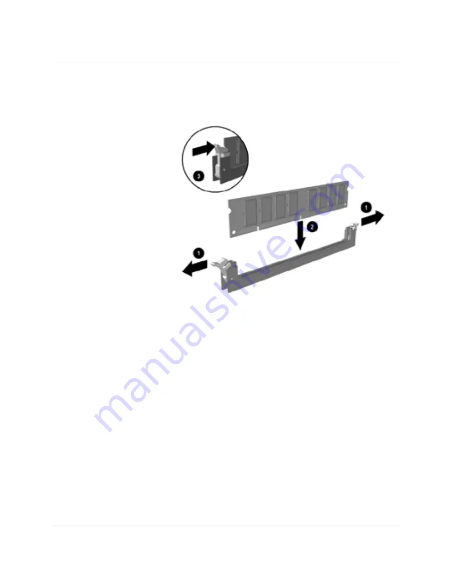
3.  Open both latches of the memory module socket 

1

, and insert the 

memory module into the socket 

2


Installing a DIMM 

Begin by installing a module into the socket nearest the 
preinstalled module, and install the modules following the 
numerical order of the sockets. 

A memory module can be installed in only one way. Match the 
notch on the module with the tab on the memory socket. Push 
the module down into the socket, ensuring that the module is 
fully inserted and properly seated 

3

2-8 

Hardware Reference Guide


Содержание 470022-515 - Evo - D300

Страница 1: ...e Reference Guide Compaq Evo Desktop Family Desktop Models Document Part Number 243850 002 January 2002 This book provides basic information for upgrading this series of computers Enhanced for accessi...

Страница 2: ...on in this document is provided as is without warranty of any kind and is subject to change without notice The warranties for Compaq products are set forth in the express limited warranty statements a...

Страница 3: ...erviceability Features 2 1 Installation Sequence 2 1 Removing the Computer Cover 2 3 Replacing the Computer Cover 2 4 Removing the Front Bezel 2 5 Removing Bezel Blanks 2 5 Installing Additional Memor...

Страница 4: ...rollers B 5 SCSI Cables B 6 Using a SCSI Cable B 6 Using SCSISelect with SCSI Devices B 6 Choosing the Quiet Drive Options B 7 C Battery Replacement D Security Lock Provisions Installing a Security Lo...

Страница 5: ...r model For a complete listing of the hardware and software installed in your computer run Compaq Diagnostics for Windows or the INSPECT utility available on some models Instructions for using these u...

Страница 6: ...Activity Light 6 Hard Drive Activity Light 2 Power Button 7 Microphone Connector optional 3 Diskette Eject Button 8 Universal Serial Bus USB optional 4 CD ROM Drive Busy Indicator 9 Stereo Headphone...

Страница 7: ...Serial Connector 6 RJ 45 Connector WARNING To reduce the risk of electric shock or damage to the equipment Do not disable the power supply cord grounding plug The grounding plug is an important safety...

Страница 8: ...Windows Used in combination with other keys to perform other functions 3 Alt Key Used in combination with another key its effect depends on the application software you are using 4 Application Key Us...

Страница 9: ...ments The pre installed Easy Access Software allows you to reprogram the Easy Access Buttons to reflect your personal preferences The buttons can be reprogrammed to any program or service of your choi...

Страница 10: ...ndows Logo Key in combination with other keys to perform certain functions available in the Windows operating systems Windows Logo Key F1 Displays a pop up menu for the selected object Windows Logo Ke...

Страница 11: ...uter has a unique serial number which may be located on the cover top 1 or the rear panel 2 of the computer Keep this number available for use when contacting Compaq customer service for assistance Se...

Страница 12: ...Product Features 1 8 Hardware Reference Guide...

Страница 13: ...e to disconnect the power cord from the wall outlet and allow the internal system components to cool before touching WARNING To reduce the risk of electrical shock fire or damage to the equipment do n...

Страница 14: ...mentation provided with the optional equipment for instructions 4 Replace the computer cover 5 Turn on the monitor computer and any devices you want to test 6 Reconfigure the computer if necessary Ref...

Страница 15: ...er outlet and disconnect any external devices CAUTION Before removing the computer cover ensure that the computer is turned off and that the power cord is disconnected from the electrical outlet 3 Loo...

Страница 16: ...he cover over the chassis then rest the guide tabs located inside the cover on the diagonal ramps at the rear of the chassis 2 Slide the cover along the ramps and into place on the chassis 3 Tighten t...

Страница 17: ...Removing the Front Bezel When replacing the front bezel ensure that the bottom hinge points are properly placed in the chassis before rotating the front bezel back into its original position Removing...

Страница 18: ...pliant SDRAM DIMMs depending on the model The SDRAM DIMMs must support CAS Latency 2 or 3 CL 2 or CL 3 They must also contain the mandatory Joint Electronic Device Engineering Council JEDEC Serial Pre...

Страница 19: ...sure that you are discharged of static electricity by briefly touching a grounded metal object Refer to Appendix E Electrostatic Discharge for more information CAUTION When handling a memory module be...

Страница 20: ...into the socket nearest the preinstalled module and install the modules following the numerical order of the sockets A memory module can be installed in only one way Match the notch on the module wit...

Страница 21: ...the computer and any external devices then disconnect the power cord from the power outlet 2 Remove the computer cover and locate the correct vacant slot in the computer chassis 3 Remove the screw sec...

Страница 22: ...er cover 3 If installing an expansion card skip to step 8 4 To remove an installed expansion card disconnect any cables attached to the expansion card 5 Remove the screw at the side of the expansion s...

Страница 23: ...the expansion card into the expansion slot and press it firmly into place When you install an expansion card make sure you press firmly on the card so that the whole connector seats properly in the e...

Страница 24: ...ird height bays for hard drives labeled as drive bays 4 and 5 4 5 Two 5 25 inch half height bays for optional drives labeled as drive bays 1 and 2 To verify the type and size of the storage devices in...

Страница 25: ...sconnect the drive power and signal cables and if it is a CD ROM or DVD ROM drive disconnect the audio connector 4 If removing a hard drive lift up on the power switch bracket then rotate down to gain...

Страница 26: ...ect hard drives to the primary controller Connect expansion devices such as CD ROM IDE tape and diskette drives to the secondary controller You may install either a third height or a half height drive...

Страница 27: ...vice 1 Shut down the operating system properly then turn off the computer and any external devices disconnect the power cord from the power outlet and remove the computer cover 2 Remove the front beze...

Страница 28: ...5 inch Drive Bay Compaq does not support mixing IDE and SCSI hard drives in the same system If you are replacing a hard drive in bay 4 or bay 5 it should be of the same type To install a hard drive i...

Страница 29: ...n to gain access to the drive bay Removing the Power Switch Bracket 4 Insert the hard drive into the bay from the front of the chassis Push it in until it locks into place Be sure that the power switc...

Страница 30: ...es 6 Connect the opposite end of the cables to the appropriate system board connector 7 Lift the power switch bracket up and into position on the front of the chassis 8 Replace the front bezel 9 Repla...

Страница 31: ...perature Range Operating Nonoperating 50 to 95 F 4 to 140 F 10 to 35 C 20 to 60 C Relative Humidity noncondensing Operating Nonoperating 20 to 80 10 to 90 20 to 80 10 to 90 Maximum Altitude unpressuri...

Страница 32: ...ut voltage select switch is required Compaq Evo Desktop Intel Pentium III Celeron Dimensions Height Width Depth 15 25 in 5 72 in 17 90 in 38 74 cm 14 52 cm 45 47 cm Approximate Weight 25 lb 11 34 kg W...

Страница 33: ...264 VAC 200 240 VAC 50 60 Hz Power Output 145 W 145 W Rated Input Current maximum 5 A 2 5 A Heat Dissipation Maximum Nominal 760 BTU hr 380 BTU hr 192 kg cal hr 96 kg cal hr This system utilizes a ful...

Страница 34: ...Specifications A 4 Hardware Reference Guide...

Страница 35: ...ctor applies only to 80 conductor ATA cables See Guidelines for Installing Ultra ATA Devices in this appendix for an example of an Ultra ATA cable Compaq hard drives ship with jumpers preset to cable...

Страница 36: ...Device 0 master drive connector 2 Device 1 slave drive connector 3 System board connector For optimal performance connect hard drives to the primary controller Connect expansion devices such as ATA CD...

Страница 37: ...Channel B if available for optimum performance SCSI cable recommendation 53 inches maximum length twisted pair LVD cable with built in terminator maximum of 5 drives with a minimum driving spacing of...

Страница 38: ...combination of internal and external SCSI devices such as hard drives tape drives and CD ROM drives Compaq does not recommend mixing different width SCSI devices on the same SCSI chain or on the same...

Страница 39: ...n this appendix or refer to the documentation included with the device Determine if the device requires that termination be enabled or disabled Set the termination if necessary See Using a SCSI Cable...

Страница 40: ...le For additional information about installing optional SCSI devices refer to the documentation included with the device option kit or contact your Compaq authorized dealer reseller or service provide...

Страница 41: ...e Quiet Drive is an optional feature and may or may not be included on your computer If this computer is equipped with a Quiet Drive or if you choose to install a Quiet Drive you may configure the dri...

Страница 42: ...ssage is displayed you must restart the computer to access the utility 3 Select your language from the list and press the Enter key 4 A choice of five headings displays in the Computer Setup Utilities...

Страница 43: ...ly To reduce the risk of personal injury Do not attempt to recharge the battery Do not expose to temperatures higher than 60 C 140 F Do not disassemble crush puncture short external contacts or dispos...

Страница 44: ...ensor 2 Shut down the operating system properly turn off the computer and any external devices disconnect the power cord from the electrical outlet and remove the computer cover or access panel It may...

Страница 45: ...ttery holder automatically secures the battery in the proper position Type 2 a To release the battery from its holder squeeze the metal clamp that extends above one edge of the battery b When the batt...

Страница 46: ...er the battery has been replaced use the following steps to complete this procedure 5 Replace the computer cover or access panel 6 Plug in the computer and turn on power to the computer 7 Reset the da...

Страница 47: ...ich vary by model Because of chassis differences the slots may be located in a different position than shown Installing Compaq Type 1 Security Bracket may vary by model WARNING To avoid injury use car...

Страница 48: ...may vary by model WARNING To avoid injury use care in handling the separated pieces of the security bracket metal edges may be sharp Be sure to install the brac that sharp edges do not extend from the...

Страница 49: ...e 2 Bracket may vary by model WARNING To avoid injury use care in handling the separated pieces of the security bracket metal edges may be sharp Be sure to install the bracket so that sharp edges do n...

Страница 50: ...Security Lock Provisions Installing a Kensington Cable Lock may vary by model Installing a Kensington Cable Lock may vary by model D 4 Hardware Reference Guide...

Страница 51: ...at static free workstations Place parts on a grounded surface before removing them from their containers Avoid touching pins leads or circuitry Always be properly grounded when touching a static sens...

Страница 52: ...onductive field service tools Use a portable field service kit with a folding static dissipating work mat If you do not have any of the suggested equipment for proper grounding contact your Compaq aut...

Страница 53: ...unit as this also restricts airflow Keep the computer away from excessive moisture direct sunlight and extremes of heat and cold For information about the recommended temperature and humidity ranges...

Страница 54: ...rn off the power If you operate the unit immediately it may malfunction while reading Avoid placing the drive in a location that is subject to high humidity extreme temperatures mechanical vibration o...

Страница 55: ...protect the drive while in transit Do not use a diskette on which you have stored or plan to store data 4 Turn off the computer and external devices 5 Disconnect the power cord from the electrical ou...

Страница 56: ...Routine Computer Care and Shipping Preparation F 4 Hardware Reference Guide...

Страница 57: ...E electrostatic discharge E 1 expansion card installing or removing 2 9 expansion slot cover removing 2 9 F features 1 1 front bezel removing 2 5 H hard drive activity light 1 2 installation guideline...

Страница 58: ...SCSI device guidelines B 3 SCSISelect utility B 6 security lock provisions D 1 serial connector 1 3 serial number location 1 7 shipping preparation F 1 specifications A 1 stereo headphone jack 1 2 sw...

Отзывы: