


JHT01 Service Manual
6-2
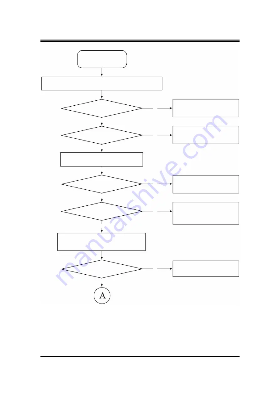
Figure 6-1 Troubleshooting flowchart (1/2)
START
Connect the AC adapter to the DC-IN socket
Is the DC-IN LED on?
No
No
No
No
No
Yes
Yes
Yes
Yes
Yes
Yes
Perform the Power Supply
Troubleshooting procedures in
section 6-2
Is the Battery LED on?
Perform the Power Supply
Troubleshooting procedures in
section 6-2
Turn the Power switch on
Is the Power On LED on?
Perform the Power Supply
Troubleshooting procedures in
section 6-2
Is the logo message display?
Perform the Display
Troubleshooting procedures in
section 6-3
If the password message displays, type the
password, then press Enter
Is Windows being loaded?
Perform diagnostics program
Содержание JHT01
Страница 1: ...Service Manual JHT01...
Страница 2: ......
Страница 3: ...Chapter 1 System Description Specification...
Страница 4: ......
Страница 6: ......
Страница 12: ......
Страница 13: ...Chapter 2 Software Specification...
Страница 14: ......
Страница 60: ......
Страница 61: ...Chapter 3 Hardware...
Страница 62: ......
Страница 63: ...Contents Chapter 3 Hardware 1 Top View 3 1 2 Bottom View 3 2...
Страница 64: ......
Страница 67: ...Chapter 4 DC DC Converter...
Страница 68: ......
Страница 70: ......
Страница 88: ......
Страница 89: ...Chapter 5 Disassembly Guide...
Страница 90: ......
Страница 92: ......
Страница 98: ...JHT01 Service Manual 5 6 4 Grasp the module and pull it out...
Страница 100: ...JHT01 Service Manual 5 8 4 Remove two screws from the bracket plate and then remove the bracket plate...
Страница 106: ...JHT01 Service Manual 5 14 3 Disconnect two screws and remove from the Modem card 4 Remove the Modem card...
Страница 113: ...JHT01 Service Manual 5 21 3 Remove the LCD module...
Страница 117: ...JHT01 Service Manual 5 25 7 Detach the LVDS cable from the back of the LCD panel...
Страница 120: ...JHT01 Service Manual 5 28 3 Lift off the logic upper...
Страница 125: ...Chapter 6 Testing and Troubleshooting...
Страница 126: ......


