background image

Visit www.commscope.com for complete specifications on all the products listed 

                    Bulletin # 7689527    Rev. G

Technical Publication

9

Section 6: 

FA-FWS-E-1 Weatherproofing Shroud Installation

1

2

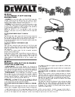
Carefully feed compression nut over DLC connector and slide onto jacketing.  

Do not twist or bend the DLC connector or fiber. Excessive force or bending may break the fiber. 

Carefully feed weather shroud body over DLC connector. 

3

Wrap the rubber split grommet around the jacketing with the stepped end towards shroud body. Push gasket into the 

clamping tynes. Approximately 0.9 mm will protrude from the tynes when fully installed.

4

Engage the compression nut one full revolution to keep the grommet in place but 

do not tighten

 fully to allow for  

adjustment during RRU connection.

5

Slide weather shroud down jacketing to allow full access to the DLC connector during the RRU connection.

If a Weather Shroud is pre-installed carefully 

remove the end cap by holding it stationary 

and turning the top nut counter-clock wise. 

Skip to step #6.

Scan to view installation video

Содержание HELIAX FiberFeed FDH1206-24SE2 Series

Страница 1: ...e and when it is needed the most in the field The FES team is staffed by an expert team of technicians who in turn are supported by some of the brightest and most experienced product line managers With all of this knowledge and support the FES offers our customers access to hands on specialized training classes Section 1 Direct Breakout Components Accessories 02 Section 2 General Specifications Co...

Страница 2: ...STANDAR HANGER FDH1210 24SE2 19256B C SSH L 42396A 1 add grommet HG 24 114 FDH1206 24SE2 19256B C SSH XL 42396A 1 add grommet HG 33 114 Fiber breakout tail NA SSH 47 43211A add grommet HG 5MM 12 Power breakout tail NA SSH 1014 43211A add grommet HG 10MM 12 Breakout Fiber tail with ODC compatible connector Equipment cabinet shelter Hybrid FiberFeed Cable Separate fiber and power conductors Maximum ...

Страница 3: ...ty Total Fiber Quantity Shielding Type Fiber Type Dimensions Cable Weight Diameter Over Jacket Breakout Length Fiber end 1 Breakout Length Power end 1 Breakout Length Fiber end 2 Breakout Length Power end 2 Physical Specifications Minimum Bend Radius loaded FDH1206 24SE2 XXX HELIAX FiberFeed UL Type TC OF ER 6 AWG 12 24 Solid copper tape Singlemode fiber 2421 kg km 1627 lb kft 36 2 mm 1 43 in 1000...

Страница 4: ... less than 3 m 1 ft below the fibre breakout point Prevent the fibre tails and power conductors from undue movement during hoisting by securing with tie ropes every 1 m 3 ft to the hoisting line During hoisting ensure that there is a free path and that the cable breakouts will not be snagged on tower members or other obstacles Installation temperature range is 20 C to 60 C 4 F to 140 F Minimum cab...

Страница 5: ...nical Publication 5 Required Apply provided Tie Wrap to the base of the hoisting grip before applying tension to the line Clevis Steel cable or rope hoist line Hoisting grip Minimum leader 5 3 M 17 ft Maximum 60 M 200 ft between hoisting grips Protective sock Hoisting Considerations Tie back ropes 1 M 3 ft ...

Страница 6: ...und the fiber ends in place until ready to make final connect of the jumper at the RRU or BBU DO NOT BEND THE FIBER ENDS TIGHTER THAN 30 mm 1 2 in BEND RADIUS ELSE THERE IS A RISK OF BREAKING THE GLASS FIBERS Attach the main cable securely to the structure or equipment using hangers to prevent strain on connections from movement in wind or snow ice conditions Ensure the fiber and power connections...

Страница 7: ...ngers as required Repeat with tails being routed to the RRU and spare fibers If additional hangers are not available slide the protection sleeve from the BBU end over any spare fibers to protect them Place tape over fiber tails and protective sleeve end to hold in place Support protection sleeve using tie wraps Connectors are fully weather sealed and do not require additional weatherizing Unused p...

Страница 8: ...Visit www commscope com for complete specifications on all the products listed Bulletin 7689527 Rev G Technical Publication 8 ...

Страница 9: ...ubber split grommet around the jacketing with the stepped end towards shroud body Push gasket into the clamping tynes Approximately 0 9 mm will protrude from the tynes when fully installed 4 Engage the compression nut one full revolution to keep the grommet in place but do not tighten fully to allow for adjustment during RRU connection 5 Slide weather shroud down jacketing to allow full access to ...

Страница 10: ...mpression nut onto jacketing to complete installation The compression nut must be tightened until it is completely against the cable gland body The grommet will protrude slightly from the compression nut Reverse steps 7 and 8 to remove sleeve for maintenance 2 1 1 2 Correct support clamp locations WARNING Remove the dust caps from DLC connector and seat into the RRU Listen for a distinct click Do ...

Страница 11: ... may cause scratches if large contamination is present Always inspect connector end face for contamination after each cleaning Clean adapter by inserting adapter cleaning stick or fiber adapter sleeve brush moistened with fiber optic cleaning solution or 91 isopropyl alcohol inside the adapter and gently pull out with twisting motion Repeat process with a dry cleaning stick Caution Do not try to c...

Страница 12: ...eving an efficient fiber optic connection 1 Perfect Core Alignment 2 Physical Contact 3 Pristine Connector Interface Today s connector design and production techniques have eliminated most of the challenges to achieving core alignment and physical contact What remains challenging is maintaining a pristine end face As a result CONTAMINATION is the 1 reason for troubleshooting optical networks Imple...

Страница 13: ...eakout NOTE Remember to slide identifier labels down the power conductors before trimming the cable to it s final length If length of cable installed needs to be adjusted you can split the cable at the BBU end using the process below and then coiling the excess fiber subunits in a storage box Patch Panel Kits are available to manage any excess fiber length in the breakouts at the BBU Excess Fiber ...

Страница 14: ...on Überprüfung Wartung oder Demontage auftreten Atenção A CommScope abdica do direito de toda responsabilidade pelos resultados de práticas inadequadas e sem segurança de instalação inspeção manutenção ou remoção Avvertenza CommScope declina eventuali responsabilità derivanti dell esecuzione di procedure di installazione ispezione manutenzione e smontaggio improprie o poco sicure CommScope 1100 Co...

Отзывы: