background image

TECP-91-008 • Rev C • January 2019

Page 13

© 2019 

CommScope

. All Rights Reserved.

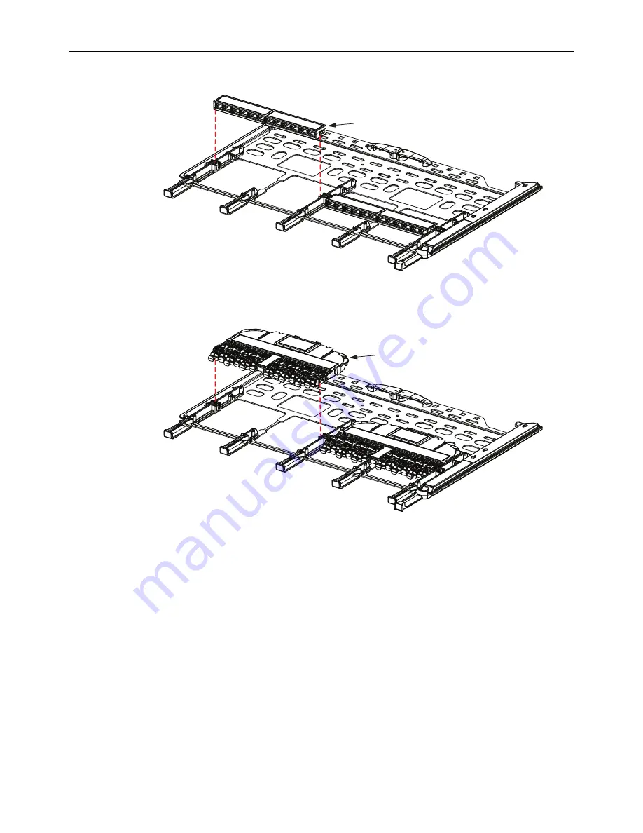
Figure 13. Installing MPO Adapter Pack

Figure 14. Installing LC-MPO Module

4. To close the blade, push in the push handle on the right side of the panel until the


blade is fully within the panel. 

MPO

ADAPTER

PACK

26411-A

LC-MPO

MODULE

26412-A

Содержание EHD

Страница 1: ...eneral Safety Precautions 3 1 PRODUCT DESCRIPTION 3 1 1 General Description 3 1 2 Major Components 3 1 3 Comparative View of 1RU 2RU and 4RU Panel 4 1 4 Specifications 6 1 5 Transportation and Storage 7 2 UNPACKING AND INSPECTION 7 3 PANEL INSTALLATION 8 3 1 Overview 8 3 2 Mounting the Panel 9 continued Content Page 26417 A TECP 91 008 Rev C January 2019 Enhanced High Density EHD Panel ...

Страница 2: ...as well as operation procedures Revision History Trademark Information CommScope logo CommScope and Enhanced High Density Panel are trademarks Applicable Standards UL 60950 1 2nd Edition 2007 03 27 Information Technology Equipment Safety Part 1 General Requirements CSA C22 2 No 60950 1 07 2nd Edition 2007 03 Information Technology Equipment Safety Part 1 General Requirements Admonishments Importan...

Страница 3: ...irst and second position The first position is used to plug in connectors to the front of an adapter pack or module The second position further removed from the front of the panel is used install adapter packs and modules and for access to clean the rear connectors when using adapter packs Danger Danger is used to indicate the presence of a hazard that will cause severe personal injury death or su...

Страница 4: ... 62 cm or 6 inches 15 24 cm Front Door swings down to provide access to the interior of the panel The door features a double hinged design that allows users to open the door without interfering with equipment below the panel on the same rack or to move the door into its lower position allowing the lowest blade to open freely Designation Label provides physical space for recording fiber designation...

Страница 5: ...TECP 91 008 Rev C January 2019 Page 5 2019 CommScope All Rights Reserved Figure 2 EHD 1RU Panel Figure 3 EHD 2RU Panel Figure 4 EHD 4RU Panel ...

Страница 6: ...igure 6 This midshelf can be removed for easier access to the bottom blades when cabling or for high count cables that will be terminated on both lower and upper blades The midshelf should be used when many trunks are terminated in the panel The midshelf prevents the weight of the trunks terminated on the top blades from weighing down on the trunks terminated at the bottom of the panel thus impedi...

Страница 7: ...to Section 7 on Page 26 if you need to contact CommScope Table 1 EHD Panel Specifications PARAMETER SPECIFICATION REMARKS Operating conditions 14 F to 140 F 10 C to 60C Humidity 10 to 95 RH No condensation Storage conditions 40 F to 158 F 40 C to 70 C Panel Dimensions and Weight 1RU panel Dimensions 21 17 in 53 76 cm D x 17 24 in 43 78 cm W x 1 72 in 4 37 cm H Weight without packaging 14 0 lb 6 4 ...

Страница 8: ...nd adapters are the preferred method If required per local standards the panel can be grounded as described in Section 3 3 on Page 10 Ground lugs and ground cables are not provided with the panel Figure 7 Mounting Options Caution This equipment is to be installed only in Restricted Access Areas dedicated equipment rooms equipment closets etc 26405 B 3 0 IN 76 2 CM 6 0 IN 152 5 CM RIGHT SIDE VIEW O...

Страница 9: ...ect two mounting screws from the accessory pack and screw the two screws into the rack bottom mounting position on each rail approximately 1 5 turns so most of the screw shank is still out b Place the open slots on the bottom of the mounting brackets onto these screws c Secure the brackets with mounting screws at higher points on the bracket Use the first full mounting hole for the top screw d Tig...

Страница 10: ...provided on the panel for a frame ground connection if required The connection must be made in accordance with local and national electrical codes Use the following procedure referring to Figure 10 1 Locate the ground location on the panel Figure 10 Grounding Location 26419 A SUPPORT CHASSIS ON SCREW SHANKS 26420 A RIGHT SIDE VIEW OF CHASSIS GROUNDING LOCATION ...

Страница 11: ...ade using methods and hardware that meets all applicable local and national electrical codes 4 OPERATION 4 1 Loading Adapter Packs or Modules For an adapter pack or module to be loaded the designated blade must be slid out to the first position and then the second position providing access to press the module or adapter pack unto the blade Use the following procedure 1 To slide out a blade to the ...

Страница 12: ...and squeeze index finger and thumb together b Slide out the blade until it stops in the second position Figure 12 Sliding Out Blade to Second Position 3 Hold the adapter pack or module above the blade align it with the blade position and press it into place as shown in Figure 13 MPO adapter pack or Figure 14 LC MPO module Note The second position also provides cleaning access to the rear of the mo...

Страница 13: ...ll Rights Reserved Figure 13 Installing MPO Adapter Pack Figure 14 Installing LC MPO Module 4 To close the blade push in the push handle on the right side of the panel until the blade is fully within the panel MPO ADAPTER PACK 26411 A LC MPO MODULE 26412 A ...

Страница 14: ... the connectors following local practice 4 When done replace the module and close the blade 4 3 Closing Blade To close a blade push in the push handle on the right side of the panel until the blade is fully within the panel 4 4 Removing Blade from Front if Required To remove a blade from the panel Figure 15 1 Deflect the tab outward on the right side of the panel 2 Pull on a gray fiber management ...

Страница 15: ...TECP 91 008 Rev C January 2019 Page 15 2019 CommScope All Rights Reserved Figure 15 Removing Blade From Front TAB 1 2 FIBER MANAGEMENT FINGER FIBER MANAGEMENT FINGER 26532 A ...

Страница 16: ...r by loosening the captive fasteners as shown in Figure 17 Figure 17 Removing the Rear Cover Note The preferred trunks for the EHD panel are CommScope trunks with gland adapters and standard breakout lengths Note Trunks entering through lower level entry points should be routed to the lower level trays within the chassis and trunks entering through higher level entry points should be routed to upp...

Страница 17: ... and pull the blade backward using the finger pull so that the blade will be accessible for connecting the trunk connectors to the adapter pack or module already installed on the blade Figure 19 Depressing the Tab Note Leave the molding plates in place The plates can be temporarily removed however if space is required not part of this procedure MOLDING PLATES TRUNK OPENINGS REMOVE CABLE ATTACHMENT...

Страница 18: ...ide only or from both sides For an example of single side entry see Figure 20 For an example of left and right cable entry see Figure 21 Figure 20 Single Entry Cable Routing Top View Figure 21 Left and Right Cable Routing Rear View Cables With Hook and Loops Shown Note Some cables are shipped with protective mesh tubing already installed as shown in Figure 22 at the cable clamp and in Figure 23 at...

Страница 19: ... Entry Point to EHD Panel 5 Starting with the lowest rear most hole remove the center knockout from the molding Slide the cable breakout through the slit on the side of the molding Before securing the cable to the rack or bracket outside of the panel make sure there is enough slack in the cable to allow the blade to be slide forward to the second position described in Section 4 2 on Page 14 ...

Страница 20: ... Shown Note Hook and loops should be installed around bundles for each tray Install where bundle begins to spread out naturally due to routing lengths Refer to Figure 21 on Page 18 Note Breakout lengths for trunks entering panel from side plates should be 30 3 in 76 2 7 62 cm CommScope trunk cables with gland adapters meet this requirement CABLES SECURED TO CABLE BRACKET ACCESSORY EHD CMB NOTE HOO...

Страница 21: ... brackets or similar method 8 Pull all blades fully forward into second position and dress cables with hook and loops 9 Push in blades and ensure unimpeded cable movement NOTE TRAYS ARE PULLED TO SECOND POSITION AND THERE IS SUFFICENT SLACK FOR TRAY MOVEMENT 26429 A NOTE MIDSHELF PREVENTS UPPER TRUNKS FROM WEIGHING DOWN ON LOWER TRUNKS AND IMPEDING THEIR MOVEMENT 26430 A HOOK AND LOOPS SECURE BREA...

Страница 22: ...shows accessories available for channel rack mounting They are as follows Figure 28 Channel Rack Mounting Accessories 26829 A FRONT OBLIQUE VIEW VERTICAL CABLE MOUNTING BRACKET FOR USE WITH COMMSCOPE TRUNKS THAT HAVE GLAND ADAPTER CABLE MOUNTING BRACKET NOTE THE MOUNTING BRACKET SHOULD BE MOUNTED SLIGHTLY ABOVE OR BELOW THE CHASSSIS AS SHOWN IN THE DETAIL BUBBLE CABLE MOUNTING BRACKET BOTTOM EDGE ...

Страница 23: ...9 shows accessories available for cabinet mounting They are as follows Figure 29 Cabinet Mounting Accessories Note When using the Vertical Cable Mounting Bracket with CommScope trunks it may be required to lengthen the breakouts on cables with 144 or less fibers and with a gland nut To do this loosen the gland adapter slide up the trunk approximately 2 3 inches 5 08 7 62 cm and remove the outer ja...

Страница 24: ...ack or cabinet The brackets can be installed either above or below the panel see Note below Select the version needed based on space considerations Refer to Figure 30 Figure 30 Cabinet Mounting Accessories Note When using the Vertical Cable Mounting Bracket with CommScope trunks it may be required to lengthen the breakouts on some trunks To do this loosen the gland adapter slide up the trunk appro...

Страница 25: ... Note The most common application is to mount the UMB bracket on the rack or cabinet such that the fanout is oriented with subunits facing down and a natural drip loop is formed when routing subunits in the panel Take caution not to exceed bend radius limitations of the fiber Refer to Figure 31 ...

Страница 26: ...dius diameters 3 8 mm When routing 12 patch cords either simplex or duplex from center to both sides 3 0 mm When routing 24 patch cords either simplex or duplex from center to one side Figure 32 Patch Cord Routing on Front of Panel 7 CONTACT INFORMATION To find out more about CommScope products visit us on the web at www commscope com For technical assistance customer service or to report any miss...

Отзывы: