


TC-96307-IP
Page 26
© 2022
CommScope
. All Rights Reserved.
4. Slide the blade fully from panel.
6.3.3
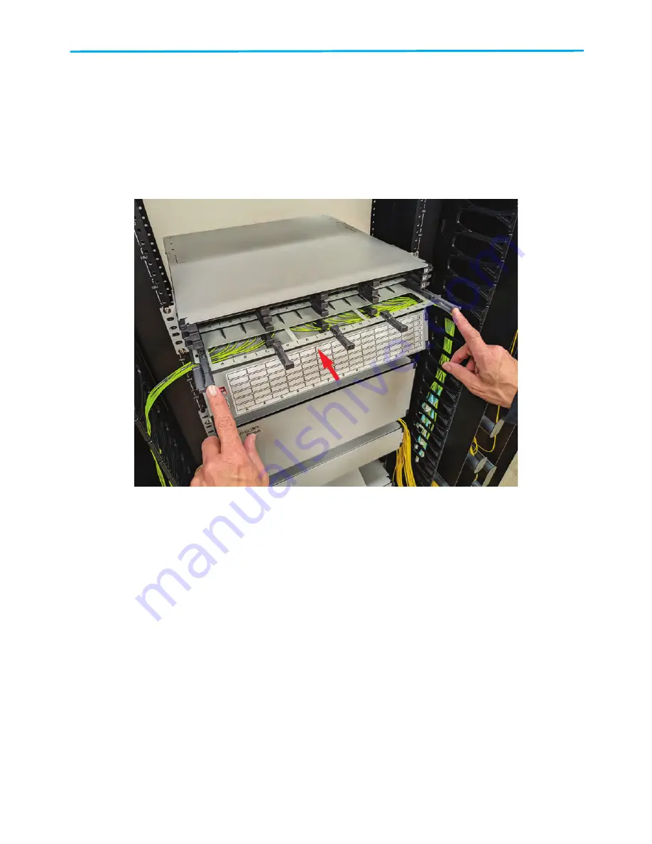
Installing a Blade
To install a blade, place it in position and slide it in until it clicks into place.
To stow blade completely,
push on both outer handles of the blade.
Refer to
.
Figure 25. Installing a Blade
6.4 Connection Components
6.4.1
Placement of Connection Components on a Blade
When installing a connection component, take care to align the grooves on the bottom of the
component with the rails on the blade, as shown in
.
6.4.2
Installing a Connection Component
To install a connection component, position it on the blade rails wherever there is space for it. Slide
the component in until it clicks into place. Refer to
.
27607-A


