


LV-66A User’s Manual System Configuration
39
Chapter 3 <System Configuration>
3.1 <SATA RAID Configuration>
The board supports four Serial ATA ports onboard, and supports RAID 0, 1, 0+1, 5 and
JBOD disk array, the RAID 0, 1, 0+1, 5 and JBOD are specified below:
RAID 0 (Stripping)
: Stripe Array is also called RAID 0, it implements a striped disk array
and the data is broken down into blocks in which each block is written to a separate disk
drive. I/O performance is greatly improved by spreading the I/O load across many channels
and drives. Best performance is achieved when data is striped across multiple channels
with only one drive per channel.
RAID 0 is not a "True" RAID because it is NOT fault-tolerant. The failure of just one drive
will result in all data in an array being lost. It should never be used in mission critical
environments.
RAID 1 (Mirroring)
: Mirror Array is also called RAID 1; it provides 100% data redundancy.
No rebuild is necessary in case of a disk failure, simply copy data from the remaining
healthy disk to the replacement disk.
You can specify a disk as the auto-selected replacement disk for a Mirror Array; this
replacement disk is called Spare Disk.
To add/remove Spare Disk for a Mirror Array, please refer to Add/Remove Spare. You can
also select an ordinary disk to replace the failed disk in a Mirror Array, instead of using a
Spare Disk for auto-replacement.
RAID 0+1
: RAID 0+1 is implemented as a mirrored array whose segments are RAID 0
arrays. It has the advantages both provided by RAID 0 (high I/O performance) and RAID 1
(fault tolerance).
At least four disks are needed to create a RAID 0+1 disk array.
RAID5 (Parity RAID)
: RAID5 Array uses block-level striping with parity data distributed
across all member disks. It requires a minimum of 3 disks to implement. It has highest read
data transaction rate and medium write data transaction rate. When one of the disks in
RAID5 failed, the data in RAID5 can also be accessed, and the broken RAID5 disk array
can be repaired with a new disk.
Содержание LV-66A
Страница 1: ...LV 66A Mini ITX Motherboard User s Manual Edition 1 02 2009 02 17 ...
Страница 6: ...LV 66A User s Manual 6 The Page is Left For Blank ...
Страница 10: ...LV 66A User s Manual Introduction 10 1 3 Mechanical Drawing ...
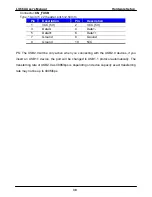
Страница 13: ...LV 66A User s Manual Hardware Setup 13 PS2 USB CRT COM USB_RJ45_1 2 AUDIO SPDIF CDIN 170mm 170mm 14 25 ...
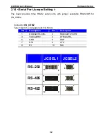
Страница 33: ...LV 66A User s Manual Hardware Setup 33 JCSEL2 JCSEL1 CN_COM2 ...
Страница 38: ...LV 66A User s Manual 38 This Page is Left For Blank ...
Страница 46: ...LV 66A User s Manual System Configuration 46 This Page is Left for Blank ...
Страница 48: ...LV 66A User s Manual I O Port Pin Assignment 48 This Page is Left for Blank ...
Страница 54: ...LV 66A User s Manual System Resources 54 Appendix C System Resources C1 I O Port Address Map ...
Страница 55: ...LV 66A User s Manual System Resources 55 ...
Страница 56: ...LV 66A User s Manual System Resources 56 C2 Memory Address Map ...
Страница 57: ...LV 66A User s Manual System Resources 57 ...
Страница 58: ...LV 66A User s Manual System Resources 58 C3 System IRQ Resources ...
Страница 60: ...LV 66A User s Manual Programming GPIO s 60 datasheet ...
Страница 62: ...LV 66A User s Manual 62 This Page is Left for Blank ...