LP-178 User’s Manual
-8-
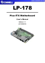
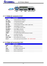
Chapter 2 <Hardware setup>
2.1 <Connector Location and Reference>
M.2 (E KEY)
CN_AUDIO DDR4
JFRNT
CN_USB
CN_LVDS
SATA_PWR
CN_SATA
CN_SMBUS CPUFAN CN_COM1/2
CN_BAT CN_LPC
DC_IN
SYSFAN
DC_OUT
Страница 1: ...LP 178 Pico ITX Motherboard User s Manual Edition 1 1 2019 09 18...
Страница 2: ...ent are property of their respective owners Disclaimer The company shall not be liable for any incidental or consequential damages resulting from the performance or use of this product The company doe...
Страница 3: ...board Including Cooler Fan 1 xUSB2 0 cable OALUSBA 3 1040173 1 x Audio cable OALPJ HDUNB 1040123 _ 1 xDC Input Power Cable OALDC B 1040513 1 x Driver CD Including User s Manual 1 x SATA SATA Power Cab...
Страница 4: ...stalling the Memory 12 2 4 I O interface 13 2 4 1 Serial ATA interface 13 2 4 2 Ethernet interface 14 2 4 3 Display interface 14 2 4 4 Serial Port interface 16 2 4 5 USB interface 17 2 4 6 Audio inter...
Страница 5: ...sors are based on the 14nm process node and offer long life availability They have a TDP of 15W and integrate Gen 9 5 Intel Graphics GT2 It allows triple independent display with 4K resolution All in...
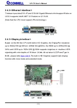
Страница 6: ...en 9 5 integrated HD Graphics Display Interface 1 x DisplayPort 1 x HDMI LAN Chip 1 x Intel I210 AT Gigabit LAN 1 x Intel I219 LM Gigabit PHY LAN Support iAMT12 0 I O Serial ATA 1 x SATA3 Audio Realte...
Страница 7: ...1 3 Block Diagram Header for LVDS or VGA PTN3460 DP HDMI DDR4 2400 SO DIMM I219 I210 2 x USB3 1 Gen2 2 x USB2 0 SPI 1 x M 2 Key E 1 x SATA ALC262 2 x RS232 LPC CPUFAN SYSFAN Super I O NCT6112D Whiske...
Страница 8: ...178 User s Manual 8 Chapter 2 Hardware setup 2 1 Connector Location and Reference M 2 E KEY CN_AUDIO DDR4 JFRNT CN_USB CN_LVDS SATA_PWR CN_SATA CN_SMBUS CPUFAN CN_COM1 2 CN_BAT CN_LPC DC_IN SYSFAN DC_...
Страница 9: ...pin header CN_SMBus 5 pin SMBus connector CPUFAN 4 pin CPU fan connector SYSFAN 4 pin System fan connector JFRNT 5 x 2 pin front panel switch indicator pin header M2 75 pin M 2 Key E slot DC_OUT 6 pin...
Страница 10: ...LP 178 User s Manual 10 2 2 Jumper Location and Reference 2 2 1 Jumper list Jumper Function JAT Power mode select JRTC CMOS Normal Clear Setting JRTC JAT...
Страница 11: ...Clear CMOS and Power on type selection JRTC Clear CMOS data jumper Jumper settings Function 1 2 Clear CMOS 2 3 Normal Default JAT AT ATX mode select jumper Jumper settings Function 1 2 AT mode 2 3 ATX...
Страница 12: ...d 1 2 Voltage Only Non ECC memory is supported In the process the board must be powered off 1 Put the memory tilt into the slot Note the Memory notch key aligned slot key 2 Then press down till lock i...
Страница 13: ...LP 178 User s Manual 13 2 4 I O interface 2 4 1 Serial ATA interface CN_SATA SATA3 10 pin connector Pin Signal 1 GND 2 TX 3 TX 4 GND 5 NA 6 NA 7 GND 8 RX 9 RX 10 GND 10 1 CN_SATA...
Страница 14: ...Based on the 8th Gen CPU with built in HD Graphics the DisplayPort resolution up to 3840x2160 60Hz or 4096x2304 60Hz the HDMI up to 4096x2304 24Hz and LVDS up to 1920x1200 60Hz supports single bus or...
Страница 15: ...pin connector Pin Signal Pin Signal 1 eDP_0 2 eDP_0 3 GND 4 eDP_1 5 eDP_1 6 GND 7 eDP_AUX 8 eDP_AUX 9 HPD 10 GND 11 3 3V There are two modules ADP 3355 and ADP 3460E you can choose the one to support...
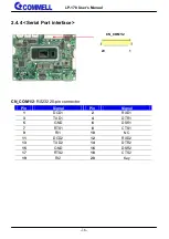
Страница 16: ...al Port interface CN_COM1 2 RS232 20 pin connector Pin Signal Pin Signal 1 DCD1 2 RXD1 3 TXD1 4 DTR1 5 GND 6 DSR1 7 RTS1 8 CTS1 9 RI1 10 NC 11 DCD2 12 RXD2 13 TXD2 14 DTR2 15 GND 16 DSR2 17 RTS2 18 CT...
Страница 17: ...User s Manual 17 2 4 5 USB interface CN_USB Front panel USB2 0 10 pin header Pitch 2 54mm Pin Signal Pin Signal 1 5VSB 2 5VSB 3 DATA0 4 DATA1 5 DATA0 6 DATA1 7 GND 8 GND 9 GND 10 Key CN_USB 1 2 9 USB3...
Страница 18: ...4 6 Audio interface CN_AUDIO Front panel audio 10 pin header Pitch 1 27mm x 2 54mm Pin Signal Pin Signal 1 MIC_L 2 GND 3 MIC_R 4 NC 5 FP_OUT_R 6 MIC_DETECT 7 SENSE 8 Key 9 FP_OUT_L 10 FP_OUT_DETECT 9...
Страница 19: ...LP 178 User s Manual 19 2 4 7 Expansion slot M2 Key E with 2 x PCI Express x1 support WI FI and Bluetooth Module M 2 E KEY...
Страница 20: ...8 Front panel switch and indicator JFRNT Front panel switch and indicator 10 pin header Pin Signal Pin Signal 1 Power_ON 2 Power_ON 3 Speaker 4 Speaker 5 HDD_LED 6 HDD_LED 7 Power_LED 8 Power_LED 9 Re...
Страница 21: ...LP 178 User s Manual 21 2 4 9 SMBus and Other Interface SYSFAN 5 1 1 5 CN_LPC 4 1 4 1 11 CPUFAN CN_SMBus 5 1 1...
Страница 22: ...MBCLK 5 GND CPUFAN CPU cooler fan 4 pin connector Pin 1 2 3 4 Signal GND 12V Sensor Control SYSFAN System cooler fan 4 pin connector Pin 1 2 3 4 Signal GND 12V Sensor Control CN_LPC LPC 11 pin header...
Страница 23: ...Power supply 2 5 1 Power input DC_IN Terminal block 2 pin power connector Pin Signal Pin Signal 1 GND 3 12V 5 2 5 2 Power output DC_OUT power 6 pin connector Pin Signal 1 12V 2 12V 3 GND 4 GND 5 5V 6...
Страница 24: ...LP 178 User s Manual 24 SATA_PWR power 6 pin connector Pin Signal 1 NC 2 NC 3 GND 4 GND 5 5V 6 5V 6 1 1 SATA_PWR...
Страница 25: ...t Page screen click Setup Utility 3 On Advanced screen click PCH IO Configuration then click Security Configuration 4 Set BIOS Lock to Disabled then save changes 5 Please make a boot able Disk which c...
Страница 26: ...r panel it needs to select the correct resolution in the BIOS If there is no fit your panel type please feedback for us to make OEM model Find the setting from Front Page Setup Utility Advanced LVDS C...
Страница 27: ...LP 178 User s Manual 27 LVDS configuration LCD Control There are 16 resolutions in LCD Panel Type For Dual boot and Legacy boot...
Страница 28: ...work for a period The integrated watchdog timer can be setup as system reset mode by program You can select Timer setting in the BIOS after setting the time options the system will reset according to...
Страница 29: ...01 activate WDTO function o 4E F0 o 4F 00 set 00 is second mode set 08 is minute mode o 4E F1 o 4F 05 00h Timeout Disable 01h Timeout occurs after 1 minute only 02h Timeout occurs after 2 second minu...
Страница 30: ...LP 178 User s Manual 30 Appendix D Hardware Monitor Find the setting from Advanced Super IO Configuration Hardware Monitor...
Страница 31: ...ave a Header for VGA or LVDS it s no need install extra driver You have to connect SMBus cable to LP 178 Please see the picture below then LVDS Configuration in BIOS Setup menu can work For further in...
Страница 32: ...e will do our best to support you for your products projects and business Taiwan Commate computer Inc Address 19F NO 94 Sec 1 Xintai 5 th Rd Xizhi Dist New Taipei City 22102 Taiwan TEL 886 2 26963909...