


LP-172 User’s Manual
-
30
-
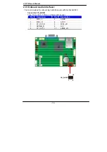
2.13 <Indicator and Switch>
The
JFRNT
provides front control panel of the board, such as power button, reset and
beeper, etc. Please check well before you connecting the cables on the chassis.
Connector:
JFRNT
Type: onboard 10-pin (2 x 5) 2.54-pitch header
Function
Signal
PIN
Signal
Power
PWRBT-
1
2
PWRBT+
Speaker
SPK-
3
4
SPK+
HDD LED
HLED-
5
6
HLED+
Power LED
GND
7
8
PWLED+
Reset
Reset-
9
10
GND
10
2
JFRNT
9
1
Содержание LP-172
Страница 1: ...LP 172 Pico ITX User s Manual 2012 03 27 Version 1 0...
Страница 6: ...LP 172 User s Manual 5 This page is left for blank...
Страница 10: ...LP 172 User s Manual 9 1 3 Mechanical Drawing...
Страница 13: ...LP 172 User s Manual 12 RJ45 PS2 CRT CN_INV DC_OUT SO DIMM LP 172...
Страница 32: ...LP 172 User s Manual 31 This Page is Left For Blank...
Страница 34: ...LP 172 User s Manual 33 This Page is Left for Blank...
Страница 38: ...LP 172 User s Manual 37 Appendix C System Resources C 1 I O Port Address Map...
Страница 39: ...LP 172 User s Manual 38...
Страница 40: ...LP 172 User s Manual 39 C 2 Memory Address Map...
Страница 41: ...LP 172 User s Manual 40 C 3 System IRQ Resources...
Страница 42: ...LP 172 User s Manual 41...
Страница 43: ...LP 172 User s Manual 42...