LE-37G User’s Manual
-8-
I/O
LE-37GXIP
LE-37GXIT
Страница 1: ...LE 37G 3 5 inch Motherboard User s Manual Edition 1 8 2017 07 24...
Страница 2: ...ent are property of their respective owners Disclaimer The company shall not be liable for any incidental or consequential damages resulting from the performance or use of this product The company doe...
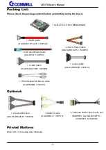
Страница 3: ...ard 1 x SATA Cable OALSATA3 H10 L35 1040523 1 x PS 2 Keyboard Mouse cable OALPS2 KM 1040131 1 xDC Input Power Cable OALDC B 1040513 1 x Audio cable OALPJ HDUNB 1040123 1 x Dual COM cable OALES BKU2NB...
Страница 4: ...the Memory 13 2 4 I O interface 14 2 4 1 Serial ATA interface 14 2 4 2 Ethernet interface 14 2 4 3 Display interface 15 2 4 4 Serial Port interface 17 2 4 5 USB interface 19 2 4 6 Audio interface 20...
Страница 5: ...ocess with MCP technology The Skylake U Kabylake U have a lower TDP it provides new HD Graphics support triple display at the same time maximum supported is up to 16GB of DDR4 better performance flexi...
Страница 6: ...210 AT Gigabit LAN 1 x Intel I219 LM Gigabit PHY LAN Support iAMT11 0 I O Serial ATA 2 x SATA3 support RAID 0 1 Audio Realtek ALC262 HD Audio Digital I O Programmable 8 bit GPIO with 12 pin header Int...
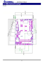
Страница 7: ...LE 37G User s Manual 6 1 3 Mechanical Drawing Positive...
Страница 8: ...LE 37G User s Manual 7 Back...
Страница 9: ...LE 37G User s Manual 8 I O LE 37GXIP LE 37GXIT...
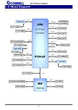
Страница 10: ...SIO NCT6106D DDI3 Channel A eDP1 2 x SATA3 SATA3 4 x USB3 0 4 x USB2 0 USB3 0 USB2 0 SPI Flash SPI PCIe x1 I219 LM HDA HD Audio PCIe x1 SATA3 LPC 1 x LPC ALC262 5 x RS232 1 x SMBUS 1 x PS 2 I210 AT PC...
Страница 11: ...or Location and Reference CN_LVDS MINI_CARD1 CN_LPC CN_AUDIO DC_IN CN_USB1 JFRNT SATA3 2 CN_COM5 6 CN_INV DC_OUT CPUFAN SMBUS MINI_CARD2 CN_COM3 4 CN_COM2 CN_DIO SO DIMM CN_PS2 SATA3 1 CN_USB2 COM1 Di...
Страница 12: ...S232 422 485 connector CN_COM3 4 20 pin RS232 connector CN_COM5 6 20 pin RS232 connector CN_USB1 2 5 x 2 pin USB2 0 pin header CN_PS2 5 x 2 pin PS 2 pin header SMBUS 5 pin SMBus connector SIMM 6 pin S...
Страница 13: ...g JMSATA MiniCard2 mSATA Setting JCSEL1 2 CN_COM2 RS232 422 485 select JP1 2 COM1 and CN_COM2 9 pin setting 2 2 2 Clear CMOS and Power on type selection JRTC Clear CMOS data jumper Jumper settings Fun...
Страница 14: ...ss the board must be powered off 1 Put the memory tilt into the slot Note the Memory notch key aligned slot key 2 Then press down till lock into the mounting notch 3 To remove the memory push outward...
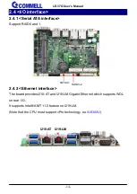
Страница 15: ...Support RAID0 and 1 2 4 2 Ethernet interface The board provides I210 AT and I219 LM Gigabit Ethernet which supports WOL on rear I O It supports Intel AMT 11 0 feature on I219 LM Note that the CPU must...
Страница 16: ...ith clone mode and extended mode Note 1 The HDMI DP dual layer connector can be changed HDMI CN_DP CN_DP function for use ADP 3355 VGA module The VGA resolution is up to 2048x1536 50Hz 2 ADP 3355 no n...
Страница 17: ...LVDS_1 11 B_LVDS_1 14 A_LVDS_1 13 B_LVDS_1 16 GND 15 GND 18 A_LVDS_2 17 B_LVDS_2 20 A_LVDS_2 19 B_LVDS_2 22 GND 21 GND 24 A_LVDS_CLK 23 B_LVDS_3 26 A_LVDS_CLK 25 B_LVDS_3 28 GND 27 GND 30 A_LVDS_3 29...
Страница 18: ...tive patterns of connection 1 2 3 4 5 6 Other may cause damage 2 4 4 Serial Port interface COM1 RS232 DB9 connector Pin Signal Pin Signal 1 DCD 2 RXD 3 TXD 4 DTR 5 GND 6 DSR 7 RTS 8 CTS 9 Set by JP1 1...
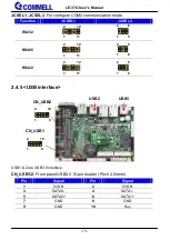
Страница 19: ...L1 and JCSEL2 to select communication mode COM3 4 5 6 RS232 20 pin header Pitch 1 27mm x 2 54mm Pin Signal Pin Signal 1 DCD1 2 RXD1 3 TXD1 4 DTR1 5 GND 6 DSR1 7 RTS1 8 CTS1 9 RI1 10 NC 11 DCD2 12 RXD2...
Страница 20: ...S485 RS422 2 4 5 USB interface USB1 2 are USB3 0 interface CN_USB1 2 Front panel USB2 0 10 pin header Pitch 2 54mm Pin Signal Pin Signal 1 5VSB 2 5VSB 3 DATA0 4 DATA1 5 DATA0 6 DATA1 7 GND 8 GND 9 GND...
Страница 21: ...Front panel audio 10 pin header Pitch 1 27mm x 2 54mm Pin Signal Pin Signal 1 MIC_L 2 GND 3 MIC_R 4 NC 5 FP_OUT_R 6 MIC_DETECT 7 SENSE 8 Key 9 FP_OUT_L 10 FP_OUT_DETECT 2 4 7 Expansion slot CN_AUDIO...
Страница 22: ...D2 to support PCIe mSATA Jumper settings Function 1 2 Support mSATA 2 3 Normal operation Default SIMM 3G MiniPcie Mode Pin Signal Pin Signal 1 SIMVCC 2 SIMRST 3 SIMCLK 4 NC 5 GND 6 SIMVPP 7 SIMDATA 2...
Страница 23: ...rnal pull up resistor 2 Input TTL level DC characteristics 5V TTL level Input Pin Parameter Sym Min Typ Max Unit Conditions Input Low Threshold Voltage Vt 0 5 0 8 1 1 V VCC 3 3V Input High Threshold V...
Страница 24: ...PC LPC 12 pin header Pitch 2 00mm Pin Signal Pin Signal 1 CLK 2 RST 3 LFRAME 4 LAD3 5 LAD2 6 LAD1 7 LAD0 8 3 3V 9 SERIRQ 10 GND 11 3 3VSB 12 NC SMBUS SMBus 5 pin connector Pin Signal 1 5V 2 NC 3 SMBDA...
Страница 25: ...ader Pitch 2 54mm Pin Signal Pin Signal 1 KB_DATA 2 M_DATA 3 NC 4 NC 5 GND 6 GND 7 VCC 8 VCC 9 KB_CLK 10 M_CLK 2 5 Power supply 2 5 1 Power input DC_IN Terminal block 2 pin power connector Pin Signal...
Страница 26: ...LE 37G User s Manual 25 2 5 2 Power output DC_OUT SATA power 4 pin connector Pin Signal 1 12V 2 GND 3 GND 4 5V DC_OUT 1 4...
Страница 27: ...tool s file name is fpt exe it s the utility that can write the data into the BIOS flash chip and update the BIOS A 2 Flash BIOS process 1 Please make a bootable UFD which can boot into DOS environmen...
Страница 28: ...5611 first for Win7 32 64 bit More information please refer https www microsoft com en us download details aspx id 38423 B 2 USB3 0 driver For 6th gen CPU The Skylake platform removed EHCI host contro...
Страница 29: ...or us to make OEM model BIOS panel type selection form BIOS Version 1 0 Single Dual channel Single Dual channel NO Type NO Type 1 640 x 480 9 1680 x 1050 2 800 x 600 10 1920 x 1200 3 1024 x 768 11 144...
Страница 30: ...nter configuration o 4E 87 o 4E 07 o 4F 07 select Logical Device o 4E 30 o 4F 08 activate GPIO function The board use GPIO3 o 4E EC o 4F XX set 01 GPIO as input set 00 GPIO as output o 4E ED o 4F XX i...
Страница 31: ...7 o 4F 08 select Logical Device o 4E 30 o 4F 01 activate WDTO function o 4E F0 o 4F 00 set 00 is second mode set 08 is minute mode o 4E F1 o 4F 05 00h Timeout Disable 01h Timeout occurs after 1 minute...
Страница 32: ...IOS set RAID mode first Advanced HDD Configuration Interface Combination RAID At boot time press CTRL I to enter the RAID configuration menu If this screen stop time is too short it can be set in the...
Страница 33: ...our best to support you for your products projects and business Taiwan Commate computer Inc Address 19F NO 94 Sec 1 Xintai 5 th Rd Xizhi Dist New Taipei City 22102 Taiwan TEL 886 2 26963909 FAX 886 2...