
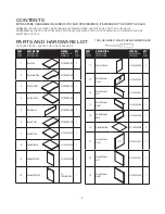


I x 8
G x 4
B x 8
A x 8
34b
I
13
I
35b
14
I
I
13
B
B
14
18
19
B B
B
B
B
B
17
A
A
A
A
A
12
A
A
A
4
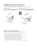
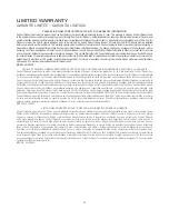
ASSEMBLY INSTRUCTION (50-100505)
DO NOT TIGHTEN SCREWS UNTIL COMPLETELY ASSEMBLED
NOTICE DE MONTAGE (50-100505) NE PAS SERRER LES VIS AVANT LE MONTAGE COMPLET
INSTRUCCIONES DE MONTAJE (50-100505) NO AJUSTE LOS TORNILLOS HASTA QUE ESTÉ COMPLETAMENTE ARMADO
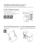
STEP / ÉTAPE / PASO 3
Insert the cam locks (B) into (13), (14), (18) and (19)
as shown. Make sure the cam lock opening is facing
the outer holes. Connect the drawer fronts (12) and
(17) using cams (A) as shown. Turn the cams about
1/2 clockwise to lock into place.
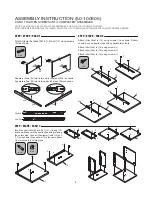
STEP / ÉTAPE / PASO 1
Attach drawer handles (28) to (12) and (17) using screws
(G) as shown.
STEP / ÉTAPE / PASO 2
Attach roller (34b) to (13) using screws (
I
) as shown. Rollers
should be on opposite sides of long horizontal cutouts.
Attach roller (35b) to (14) using screws (
I
).
Attach roller (34b) to (18) using screws (
I
).
Attach roller (35b) to (19) using screws (
I
).
34b
35b
34a
35a
28
28
12
17
G
G
Separate rollers (34) into its two parts (34a) and (34b) as shown.
Separate rollers (35) into its two parts (34a) and (34b) as shown.
34a/35a
34b/35b
34b
18
I
I
35b
19
I
I


